Cooling arrangement for an offshore wind energy installation

a cooling arrangement and wind energy technology, applied in the direction of domestic cooling apparatus, lighting and heating apparatus, electric generator control, etc., can solve the problems of frequent problems, high maintenance costs of such cooling arrangements for offshore wind energy installations, and loss of efficiency during current generation by generators, so as to prevent blockage

Inactive Publication Date: 2005-01-13
RITTALWERK RUDOLF LOH GMBH & CO KG
View PDF22 Cites 17 Cited by
  • Summary
  • Abstract
  • Description
  • Claims
  • Application Information

AI Technical Summary

Benefits of technology

[0020] In order to prevent particularly coarse particles from entering the cooling circuit of the heat-dissipating device, a screen, a rake, or the like, which prevents the entry of particles into the cooling circuit, can be arranged at the first opening and / or the second opening of the cooling circuit. With interplay with the step wherein the flow direction within the open cooling circuit of the heat-dissipating device is reversed, the screen, rakes, etc. are also flushed and thus their blockage is prevented.

Problems solved by technology

The occurring losses of efficiency during the generation of current by the generator appear in the form of heat.
Although the heat removal with the aid of the seawater, which is available in sufficient quantities, is very effective, it entails one disadvantage that maintenance of such cooling arrangements for offshore wind energy installation is very expensive, in particular because of heavy algae and mollusk infestation.
However, problems often arise because of blockage of these filters by biological material or other particles present in the ambient waters.

Method used


Image

  • Cooling arrangement for an offshore wind energy installation
  • Cooling arrangement for an offshore wind energy installation
  • Cooling arrangement for an offshore wind energy installation

Examples


Embodiment Construction

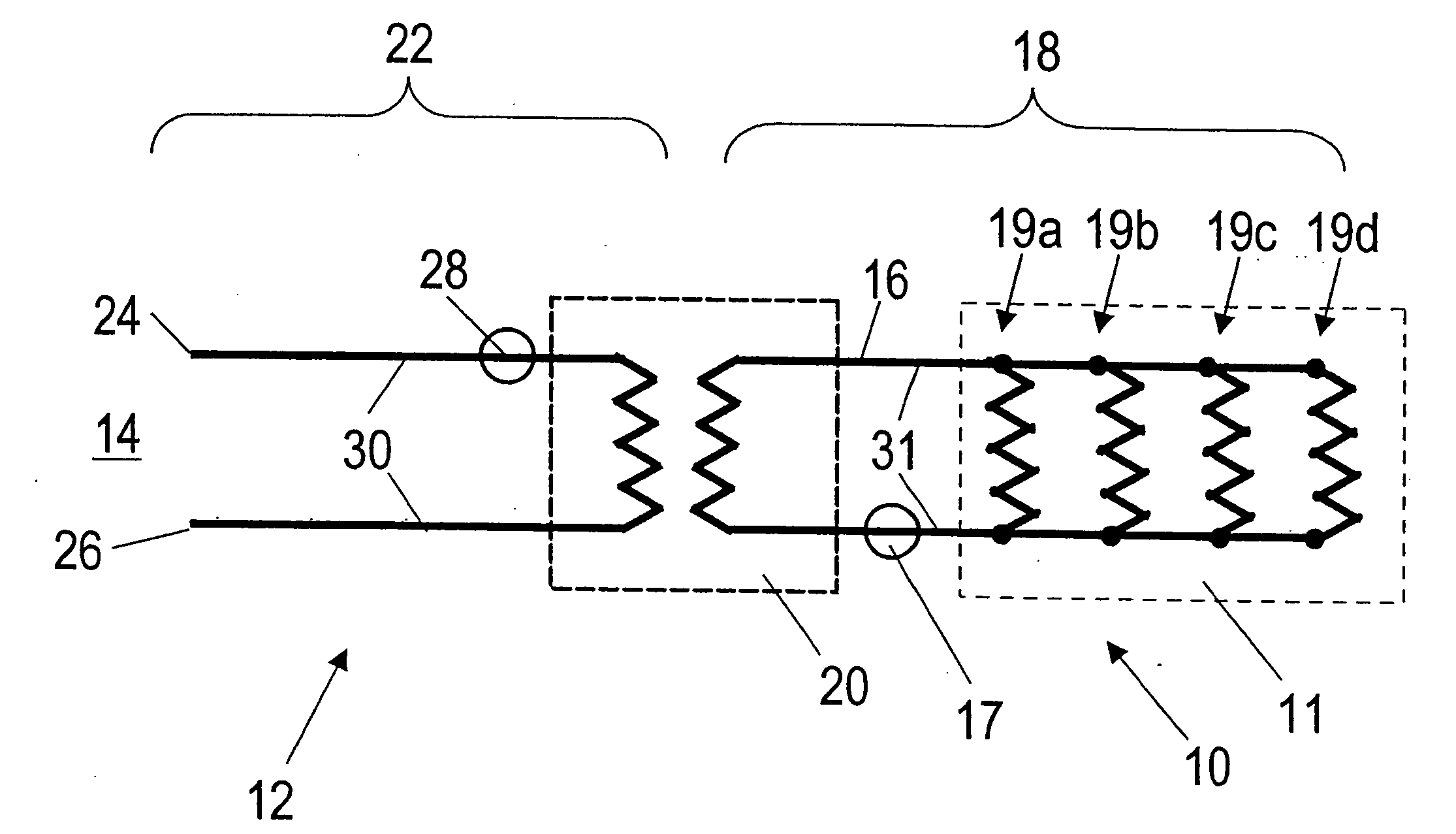
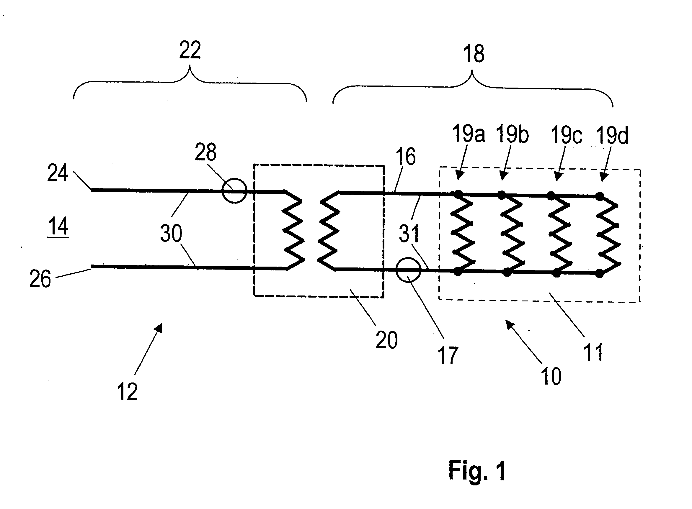
[0024]FIG. 1 shows a cooling device for an offshore wind energy installation in a schematic lateral view and in section. A generator unit 11, driven by a rotor, not shown, is arranged in the gondola, not shown, of a tower-shaped offshore wind energy installation. The generator unit is used for generating current, during which heat is released because of losses in efficiency, which is absorbed by a heat-absorbing device 10 operating with a coolant 16 supplied with antifreeze. In addition, waste heat, for example from switchgear cabinets, must be removed, or electronic circuits must be cooled.

[0025] The closed cooling circuit 18 of the heat-absorbing device 10 includes four air / coolant heat exchangers 19a, 19b, 19c and 19d, which can be arranged at the generator 11 and at associated switchgear cabinets and at mechanical components which are heated by waste heat or frictional heat. The heat to be removed can be transferred via the spatially close contact of the components to be cooled...


PUM


Abstract

A cooling arrangement for an offshore wind energy installation, having a heat-absorbing device for absorbing heat generated by the electronic devices and/or the mechanical devices of the offshore energy installation, which is to be removed, and a coupled heat-dissipating device for dissipating heat to the surrounding water. The heat-absorbing device has a first cooling circuit operated by a fluid coolant which, in a heat exchanger device, transfers the absorbed heat to the heat-dissipating device having an open second cooling circuit operated with the ambient water as the coolant. A plurality of electrodes are arranged on the inner walls of the conduits of the second cooling circuit, which are spaced apart from each other in its extension direction, each of which is connected with a voltage supply device for generating an alternating high voltage between at least two of the electrodes.

Description

BACKGROUND OF THE INVENTION [0001] 1. Field of the Invention [0002] This invention relates to a cooling arrangement for an offshore wind energy installation, having a heat-absorbing device for absorbing the heat generated by the electronic and / or mechanical devices of the offshore energy installation, to be removed, and a coupled heat-dissipating device for dissipating heat to the surrounding water. The heat-absorbing device has a first cooling circuit operated by a fluid coolant which, in a heat exchanger device, transfers the absorbed heat to the heat-dissipating device having an open second cooling circuit operated by ambient water as the coolant. [0003] 2. Discussion of Related Art [0004] An offshore wind energy installation with a heat exchanger system is described by German Patent Reference DE 100 16 913 A1. The tower-shaped offshore wind energy installation has a rotor unit, a gear arrangement and a connected generator for current generation. The occurring losses of efficienc...

Claims


Application Information

Patent Timeline
Patent Type & Authority Applications(United States)
IPC IPC(8): F03D9/00F03D11/00F25D9/00H05K7/20
CPCF03D11/00Y02E10/722F05B2260/20F05B2240/95F03D80/60Y02E10/72Y02E10/727
Inventor RURUP, JORN
Owner RITTALWERK RUDOLF LOH GMBH & CO KG
Why Eureka
Try Eureka