Method of preparing components, prepared component, lithographic apparatus and device manufacturing method

a technology of lithographic apparatus and device manufacturing, which is applied in the direction of printers, instruments, photographic processes, etc., can solve the problems of large amount of outgasing and reduce the efficiency of nearby actuators, and achieve the effect of reducing the problems associated

Inactive Publication Date: 2005-01-13
ASML NETHERLANDS BV
View PDF22 Cites 9 Cited by
  • Summary
  • Abstract
  • Description
  • Claims
  • Application Information

AI Technical Summary

Benefits of technology

[0017] It would therefore be desirable to provide a way of reducing

Problems solved by technology

Non-metallic materials are used because metallic materials can reduce the efficiency of nearby actuators (e.g. linear motors) and are a so

Method used


Image

  • Method of preparing components, prepared component, lithographic apparatus and device manufacturing method
  • Method of preparing components, prepared component, lithographic apparatus and device manufacturing method
  • Method of preparing components, prepared component, lithographic apparatus and device manufacturing method

Examples


examples

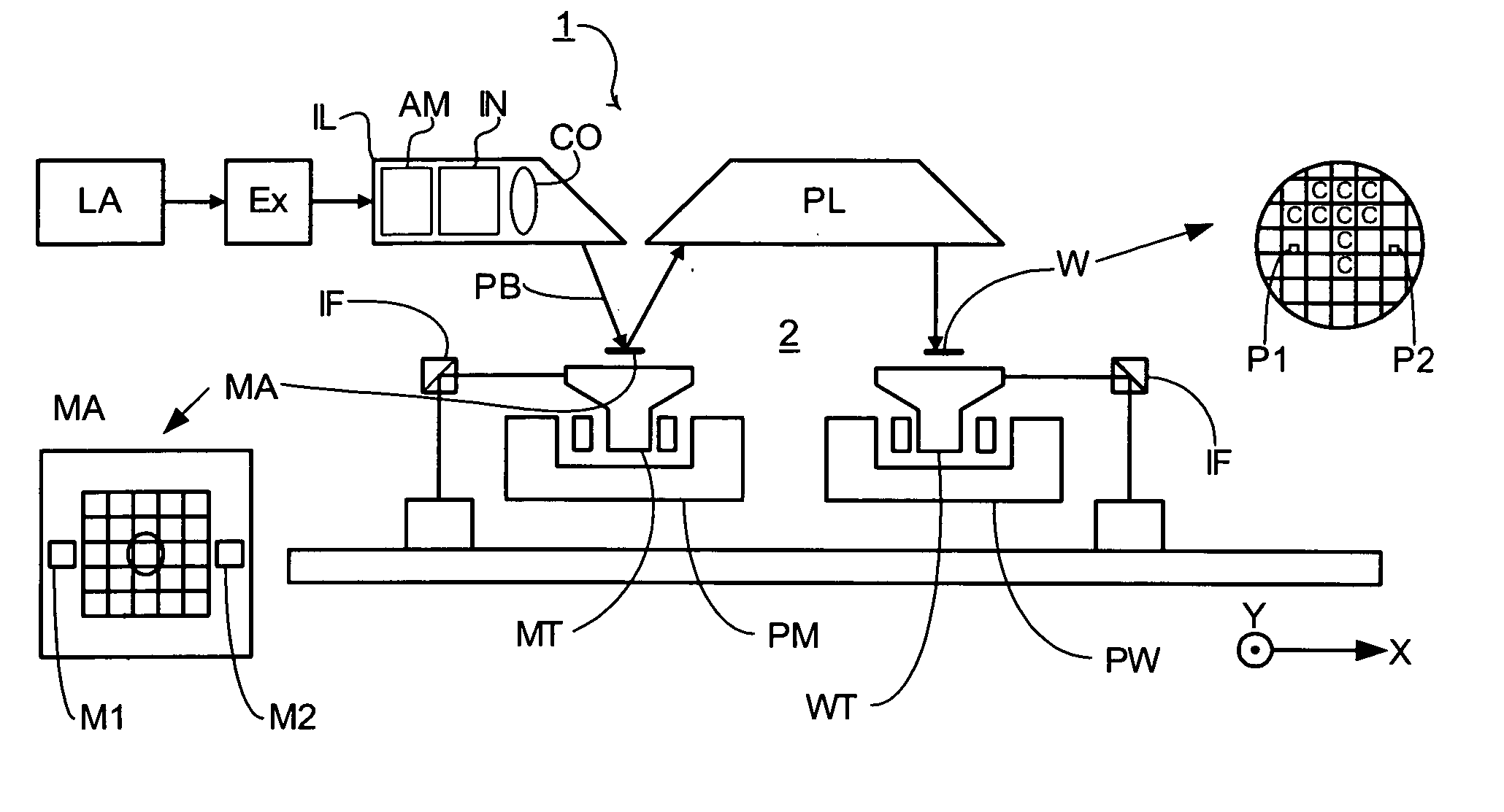
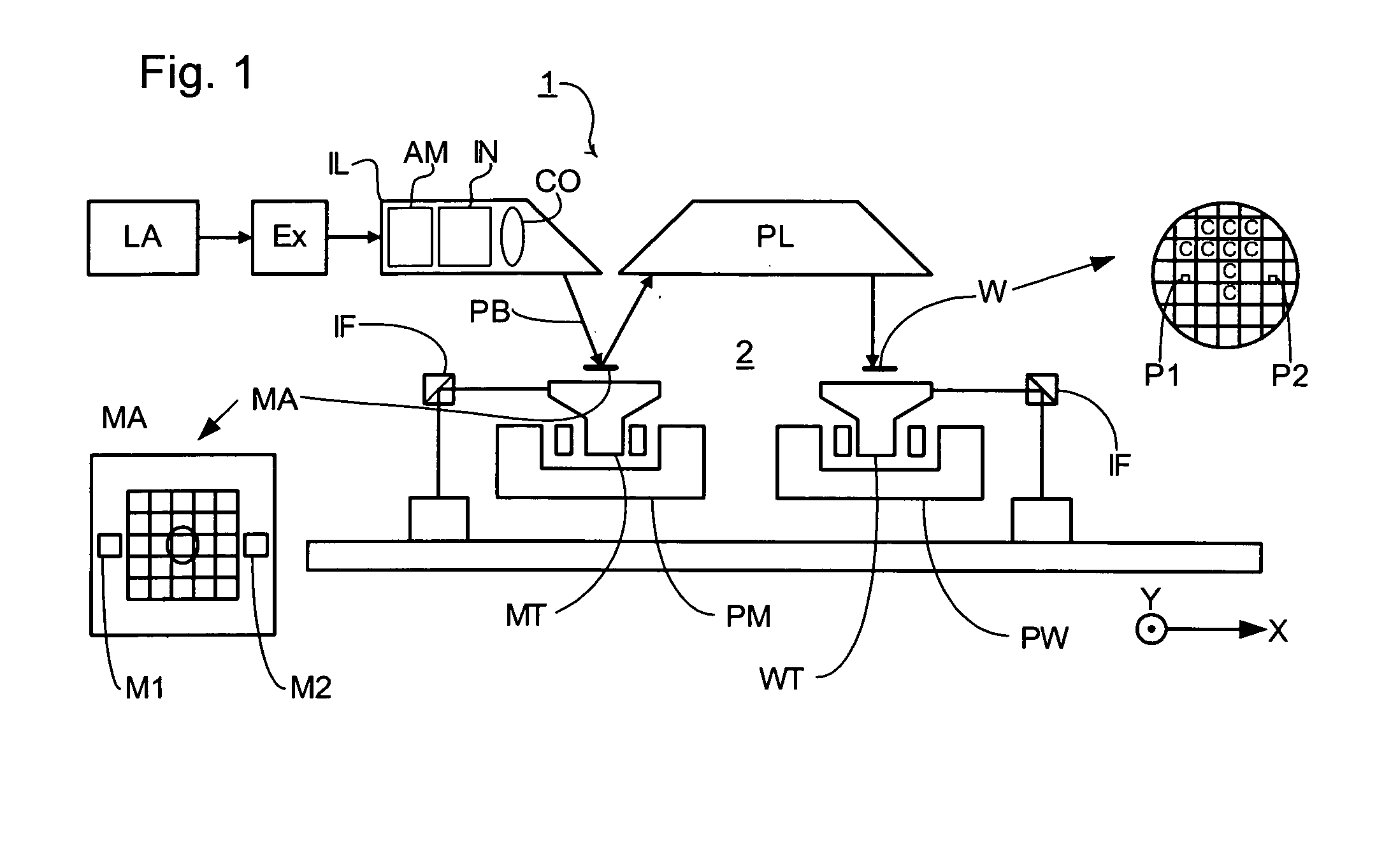
[0073] FIGS. 2 to 13 show various examples of the invention applied to components used in an actuator system.

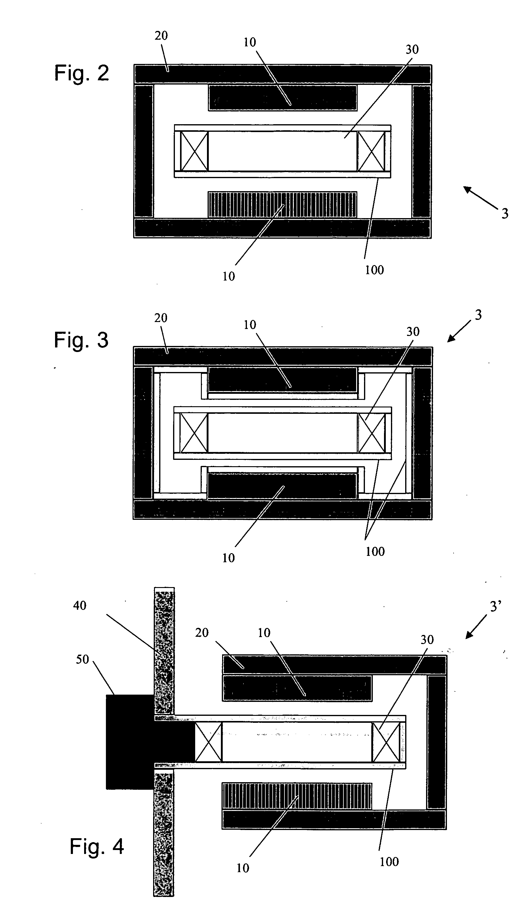
[0074]FIGS. 2 and 3 show an enclosed actuator system 3 in which the central component comprising the coil 30 moves with respect to the yoke 20 in a direction perpendicular to the plane of the drawing. The inner chamber is held in a vacuum and, to reduce outgassing, the coil 30 can be coated with a coating 100 as described above (see FIGS. 2 and 3). The coil 30 in each of these examples is typically glued to its support component using an epoxy-based resin and for this reason, coatings that can be applied and treated using low temperature steps (e.g. less than 200° C.) are preferred. The internal parts of the yoke 20 and magnet 10 can also be coated, as shown in FIG. 3.

[0075] A second type of actuator 3′ is shown in FIGS. 4 to 6. Here, the central component is fixed to a chamber wall 40 and the yoke component 20 moves around it in a direction perpendicular to the plane of th...


PUM


Abstract

A method of preparing components for use in a vacuum chamber of a lithographic apparatus is disclosed. The method includes coating the component with a non-metallic material. The method may further include treating the coating so as to harden the coating. Preferably, the coating material is a hydrogen silsesquioxane (HSQ), which may be applied via spraying, brushing, or spinning and can be treated by heating or by irradiation with an electron beam. The resulting components strongly reduce outgassing of water and hydrocarbons when subjected to a vacuum environment.

Description

CROSS-REFERENCE TO RELATED APPLICATIONS [0001] This application claims the benefit of priority from European Patent Application No. 03252894.5, filed May 9, 2003, the content of which is incorporated herein by reference in its entirety. BACKGROUND OF THE INVENTION [0002] 1. Field of the Invention [0003] The present invention relates to a method of preparing components for use in a lithographic projection apparatus. [0004] 2. Description of Related Art [0005] The term “patterning device” as here employed should be broadly interpreted as referring to a device that can be used to endow an incoming radiation beam with a patterned cross-section, corresponding to a pattern that is to be created in a target portion of the substrate; the term “light valve” can also be used in this context. Generally, the pattern will correspond to a particular functional layer in a device being created in the target portion, such as an integrated circuit or other device (see below). Examples of such pattern...

Claims


Application Information

Patent Timeline
IPC IPC(8): G03F7/20H01L21/027
CPCG03F7/70983G03F7/70916G03F7/70908
Inventor DAMS, JOHANNES ADRIANUS ANTONIUS THEODORUSKROON, MARKVOORMA, HARM-JANSPEE, CAROLUS IDA MARIA ANTONIUS
Owner ASML NETHERLANDS BV
Why Eureka
Try Eureka