
Device and method for analyzing ion channels in membranes

Inactive Publication Date: 2005-01-13
FERTIG NIELS +2
View PDF2 Cites 28 Cited by
  • Summary
  • Abstract
  • Description
  • Claims
  • Application Information

AI Technical Summary

Benefits of technology

[0009] When such a biochip is used, the use of a pipette whose comparatively long shaft leads to a high stray capacitance can be dispensed with. The critical geometrical parameters can, however, be optimized from the very beginning, and this has the effect that the signal-to-noise ratio will be improved markedly in comparison with the prior art whereby the timing resolution will be improved. This applies to biochips with a single opening, i.e. for M=N=1 as well as to biochips with a plurality of openings, i.e. M>1 and / or N>1.
[0076] The above-described measuring probes can advantageously be implemented in such a way that they comprise a means for generating a vacuum in the glass tube or the holding device. With the aid of this means, a membrane patch of a cell, which is also in solution, can be defined by the usual suction technique. This means that all the steps required for carrying out an analysis of ion channels can be executed at a single device. This leads to improved handling properties of the device.

Problems solved by technology

The known device is, however, disadvantageous insofar as it is not suitable for simultaneously analyzing a large number of substances or the effect of a substance on a large number of different (e.g. genetically modified) ion channels.
The known device is therefore not suitable for high throughput analyzing.
Hence, this device is can be used for substance screening in the pharmaceutical industry only to a very limited extent.
Another disadvantage of the known device is that the time scale on which the opening and closing mechanisms in the ion channels take place is accessible only to a very limited extent with this device consisting of a glass pipette, an electrode and an amplifier.
This has the effect that, when this device is used for the patch clamp method, the bandwidth will be limited to less than 100 kHz.

Method used


Image

  • Device and method for analyzing ion channels in membranes
  • Device and method for analyzing ion channels in membranes
  • Device and method for analyzing ion channels in membranes

Examples


first embodiment

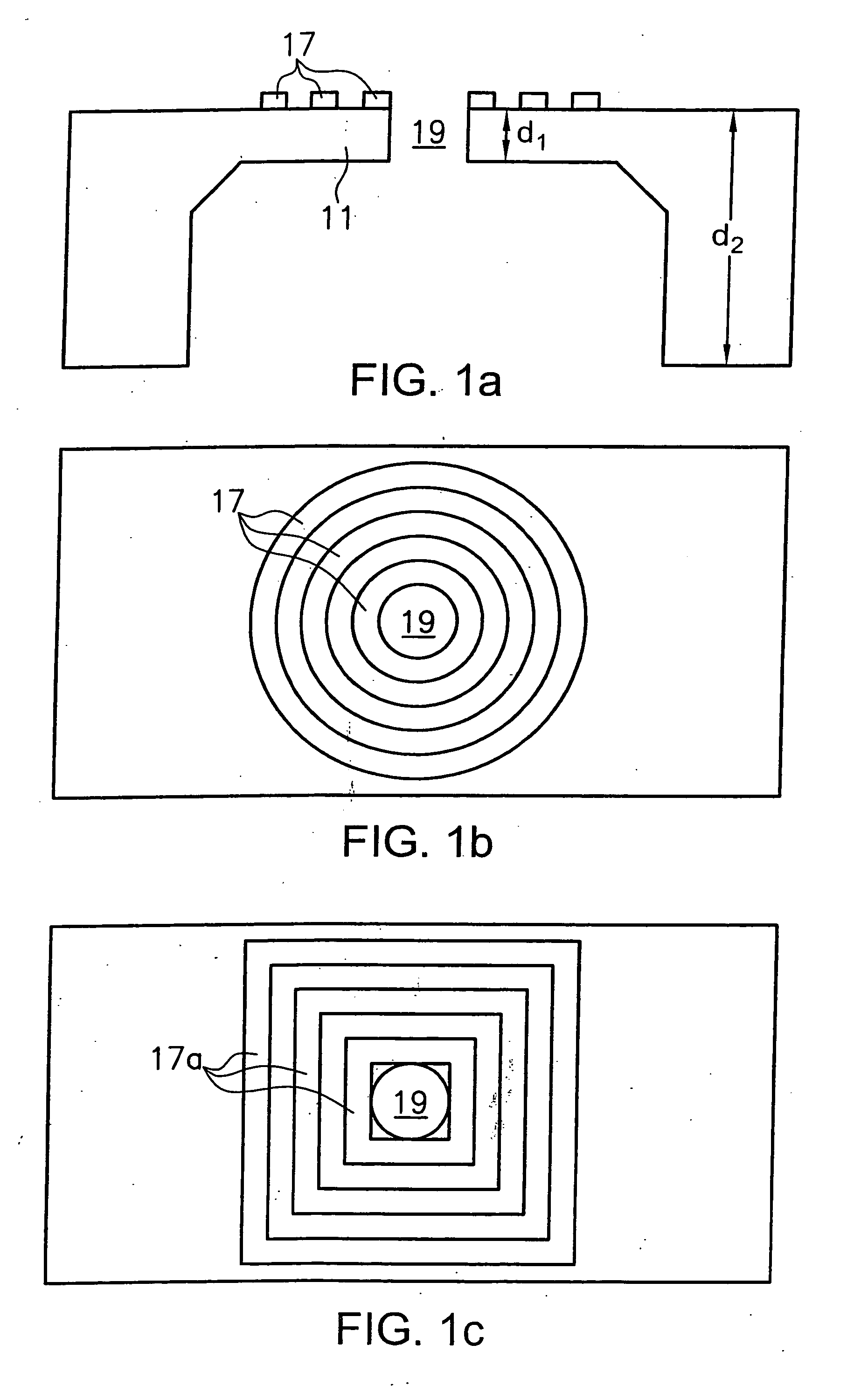
[0078]FIG. 1a shows a sectional view of a biochip according to the present invention;

[0079]FIG. 1b shows a top view of said first embodiment of a biochip according to the present invention;

[0080]FIG. 1c shows a top view of a modification of the first embodiment of a biochip according to the present invention;

second embodiment

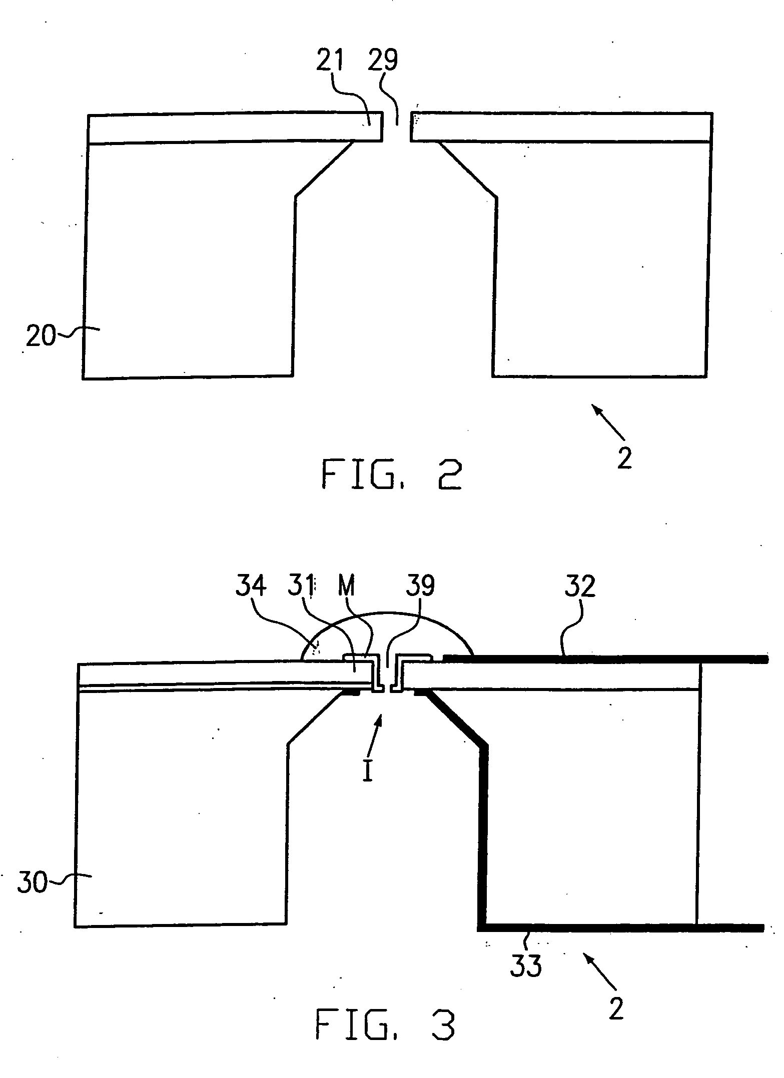
[0081]FIG. 2 shows the biochip according to the present invention;

third embodiment

[0082]FIG. 3 shows the biochip according to the present invention;

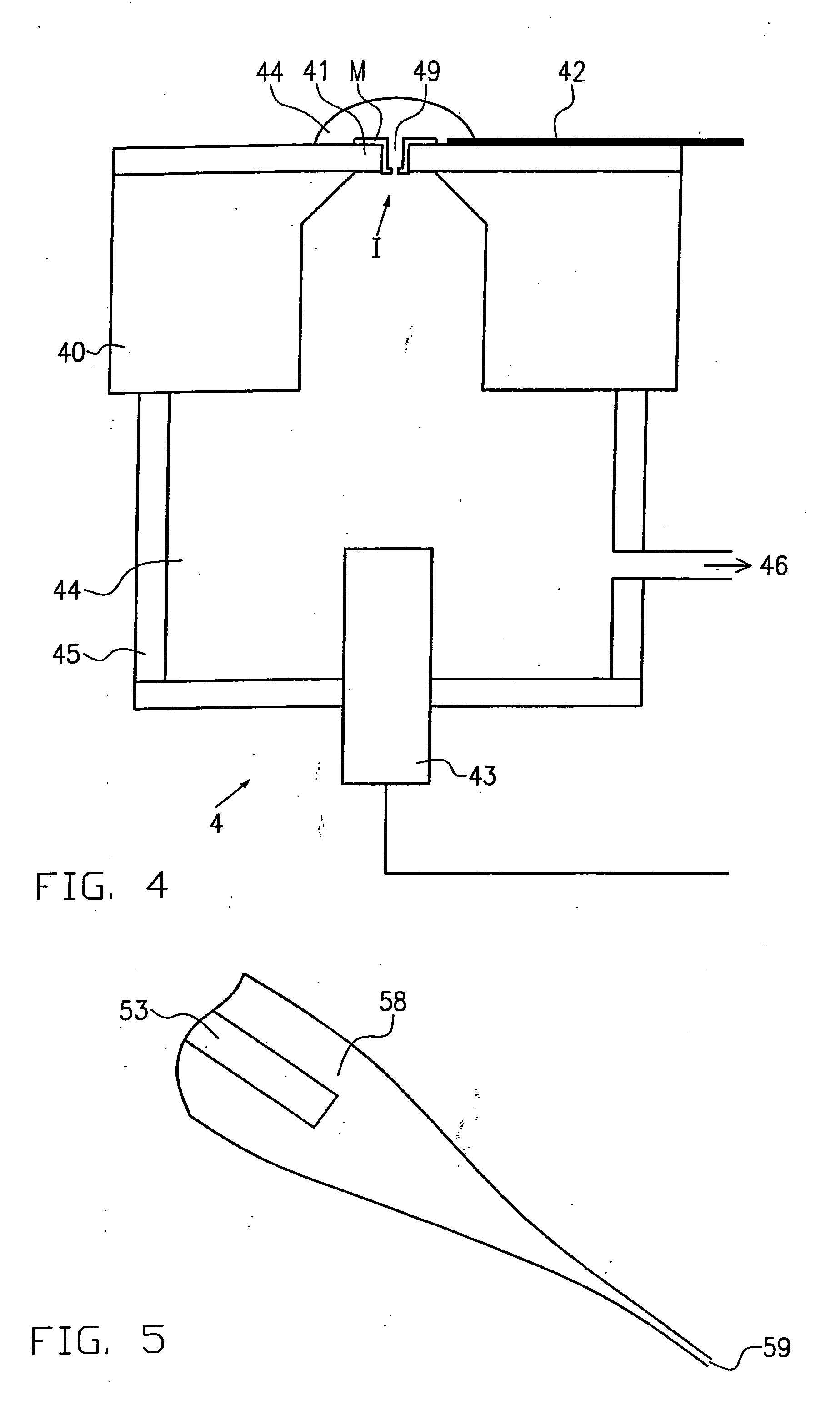
[0083]FIG. 4 shows an embodiment of the measuring probe according to the present invention; and

[0084]FIG. 5 shows a pipette for analyzing ion channels according to the prior art.

[0085]FIG. 1a and 1b show a first embodiment 1 of a biochip according to the present invention.

[0086] This biochip comprises a substrate formed with an opening 19 for receiving therein a cell membrane which comprises at least one ion channel. In the present case, the biochip is shown with M=N=1.

[0087] The substrate comprises a base portion 10 with a first thickness d, and a window portion 11 with a second thickness d2 in which the opening 19 is provided.

[0088] The thickness of the base portion 10 ranges from 1 mm to 100 μm and the thickness of the window portion ranges from 1 μm to 50 nm. The window portion has an area of a few 10 μm2 to 0.1 mm2.

[0089] The opening 19 is substantially circular and has a diameter which ranges from 10 μm to ...


PUM


Abstract

The present invention relates to devices and methods for analyzing ion channels in membranes. The invention is characterized by a biochip comprising a substrate in which openings are provided in the form of an M×N matrix for receiving therein a cell membrane including at least one ion channel (I) or an artificial lipid membrane (Me), wherein M≧1 and N≧1.

Description

FIELD OF THE INVENTION [0001] The present invention relates to devices and methods for analyzing ion channels in membranes, in particular devices and methods for executing the so-called patch clamp technique with the aid of a biochip, especially for use in high throughput processes. PRIOR ART [0002] Ion channels are membrane proteins which serve as switchable pores for a flow of current. Ion channels, which are the smallest excitable biological structures, especially constitute the fundamental switching elements of the nervous system. It follows that the equipment of a neurocyte with ion channels of different types essentially determines the neurocyte's role in the processing of information in the brain. This applies, by the way, also to non-neuron excitable cells in a similar manner, e.g. to those of the cardiac muscle and its stimulus conduction systems. Switching processes in ion channels are analyzed for obtaining e.g. information on possible malfunctions and their elimination b...

Claims


Application Information

Patent Timeline
IPC IPC(8): C12M1/34G01N33/487
CPCG01N33/48728
Inventor FERTIG, NIELSBEHRENDS, JANBLICK, ROBERT
Owner FERTIG NIELS
Learn More