Ion irradiation of a target at very high and very low kinetic ion energies

a target and ion energy technology, applied in the field of ion irradiation apparatus, can solve the problems of difficult ion-optical treatment of high-energy ions, reducing the lifetime of ions, etc., and achieves the effects of reducing chromatic aberration, reducing image aberration, and reducing ion-optical treatment difficulty

Active Publication Date: 2005-01-20
IMS NANOFABTION
View PDF8 Cites 56 Cited by
  • Summary
  • Abstract
  • Description
  • Claims
  • Application Information

AI Technical Summary

Benefits of technology

[0013] Another major advantage of the invention is that with multiply charged ions, the imaging aberrations are reduced. Chromatic aberrations are drastically reduced due to the high kinetic energy imparted to the ions. Moreover, the effect of stochastic blur is reduced, as it is approximately proportional to m0.3 and q−1.3, where m is the mass of the ion, and q its electrical charge. Thus, for instance by using Ar18+instead of He+ions, a reduction of the stochastic blur by a factor of 20 is reached.
[0014] On the other hand, when a deceleration of the ions is used, the same system allows very low energies at the substrate, and the length of the reduction optics can be reduced dramatically due to the low particle energies, and consequently the space charge related blur such as stochastic interaction is reduced in a corresponding way.
[0015] The deceleration means either before or after the mask level reduce the energy in the subsequent projection system, which allows a miniaturized fabrication of the projection system and, as a consequence, to an improved optical performance. Preferably, the acceleration / deceleration means is positioned immediately in front of the mask or pattern definition means, as seen along the direction of the beam.
[0016] Thus, for patterning at high kinetic energies, the projection system comprises an acceleration means containing an electric field oriented substantially parallel to the path of the structured beam. The illumination system may additionally comprise a deceleration means, which leads to reduced energy at the mask level avoiding unwanted transmission of the ions through the stencil mask and irradiation damage, the mask consisting for example of a membrane structure with small openings. On the other hand, for low-energy purposes, the illumination system comprises a deceleration means which leads to reduced energy of the particles entering the projection system. The alternative deceleration means after the mask level allows higher energies at the mask level to avoid effects such as deflection by charging up phenomena and scattering by dielectric interaction with the mask when going through the openings (image charge interaction).

Problems solved by technology

Contact masks have various problems, in particular that the pattern to be formed on the target must be present in the mask at the same scale; also, the irradiation of a mask with the high-energy ions would drastically reduce its lifetime.
However, ion-optical treatment of ions of these high energies would be difficult in a state-of-the-art ion-beam lithography apparatus since it would require correspondingly higher voltages in the electrostatic lenses used.

Method used


Image

  • Ion irradiation of a target at very high and very low kinetic ion energies
  • Ion irradiation of a target at very high and very low kinetic ion energies
  • Ion irradiation of a target at very high and very low kinetic ion energies

Examples


Embodiment Construction

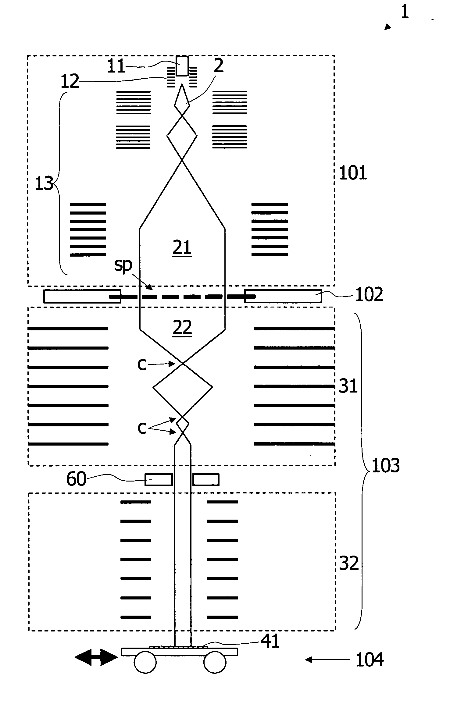
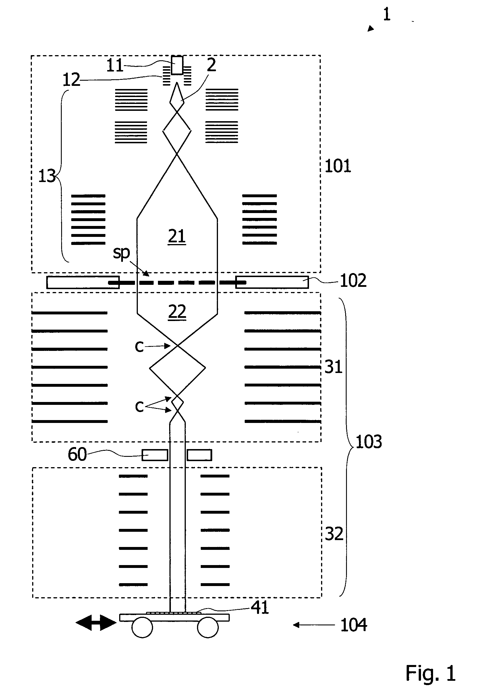
[0025] An overview of an implantography apparatus 1 according to a first preferred embodiment of the invention is shown in the schematic overview of FIG. 1. In the following, only those details are given as needed to disclose the invention; for the sake of clarity, the components are not shown to size in FIG. 1. The main components of the implantography apparatus 1 are—corresponding to the direction of the ion beam 2 which runs vertically downward in FIG. 1—an illumination system 101, a pattern definition system 102, a projecting system 103 comprising a demagnifying projection system 31 and an acceleration system 32, and a target station 104 with the target 41. The whole apparatus 1 is contained in a vacuum housing (not shown) held at high vacuum to ensure an unimpeded propagation of the beam 2 along the optical axis of the apparatus. In the embodiment shown, the particle-optical systems 101,103 are largely realized using electrostatic lenses; it should be noted that other implement...


PUM

PropertyMeasurementUnit
energy lossaaaaaaaaaa
sizesaaaaaaaaaa
transparentaaaaaaaaaa

Abstract

A particle-beam exposure apparatus (1) for irradiating a target (41) by means of a beam (2) of energetic electrically charged particles comprises: an illumination system (101) for generating and forming said particles into a directed beam (21); a pattern definition means (102) located after the illumination system for positioning a pattern of apertures transparent to the particles in the path of the directed beam, thus forming a patterned beam (22) emerging from the pattern definition means through the apertures; and a projection system (103) positioned after the pattern definition means (102) for projecting the patterned beam (22) onto a target (41) positioned after the projection system. The apparatus further comprises an acceleration/ deceleration means (32) containing an electric potential gradient which is oriented substantially parallel to the path of the structured beam and constant over at least a cross-section of the beam.

Description

FIELD OF THE INVENTION AND DESCRIPTION OF PRIOR ART [0001] The present invention relates to an apparatus for irradiating a target with ions, in particular for implanting ions into the target. More particularly, the invention relates to a particle-beam exposure apparatus for irradiating a target by means of a beam of energetic electrically charged particles, comprising an illumination system for generating and forming said energetic particles into a directed beam, a pattern definition means located after the illumination system as seen along the direction of the beam, said pattern definition means being adapted to position a pattern composed of apertures transparent to the energetic particles in the path of the directed beam, thus forming a patterned beam emerging from the pattern definition means through the apertures, and a projection system positioned after the pattern definition means and adapted to project the patterned beam onto a target positioned after the projection system. ...

Claims


Application Information

Patent Timeline
Patent Type & Authority Applications(United States)
IPC IPC(8): G03F7/20H01J37/305H01J37/317H01L21/027
CPCB82Y10/00B82Y40/00H01J37/3174H01J2237/04735H01J2237/047H01J2237/0473H01J2237/0453
Inventor PLATZGUMMER, ELMARSTENGL, GERHARDLOESCHNER, HANS
Owner IMS NANOFABTION
Why Eureka
Try Eureka