Channel spark source for generating a stable focussed electron beam

a channel spark source and electron beam technology, applied in the direction of spark plugs, discharge tube main electrodes, therapy, etc., can solve the problem of insufficient power density for effective ablation

Active Publication Date: 2005-01-20
KERNFORSCHUNGSZENTRUM KARLSRUHE GMBH
View PDF4 Cites 26 Cited by
  • Summary
  • Abstract
  • Description
  • Claims
  • Application Information

AI Technical Summary

Benefits of technology

[0007] In a channel spark source triggered by gas discharge for generating a stable focused electron beam, a gas supply for a hollow cathode thereof is provided which generates in the hollow cathode a pressure differential so that the multiplication of charge carriers in a trigger plasma of a trigger plasma source connected to the hollow cathode provides for a reliable gas discharge and the formation of a stable electron beam which exits the arrangement which does not damage the internal passages of the arrangement.

Problems solved by technology

However, in this phase, the energy content of the beam, that is, the power density is insufficient for an effective ablation.

Method used


Image

  • Channel spark source for generating a stable focussed electron beam
  • Channel spark source for generating a stable focussed electron beam
  • Channel spark source for generating a stable focussed electron beam

Examples


Embodiment Construction

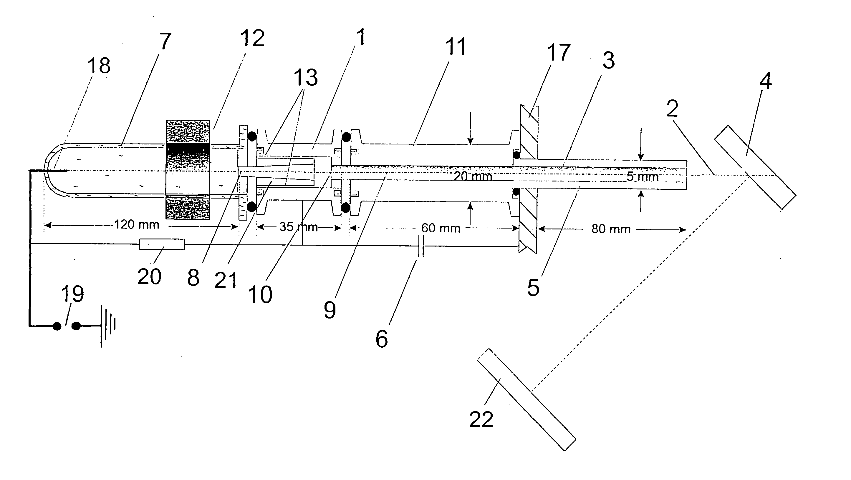
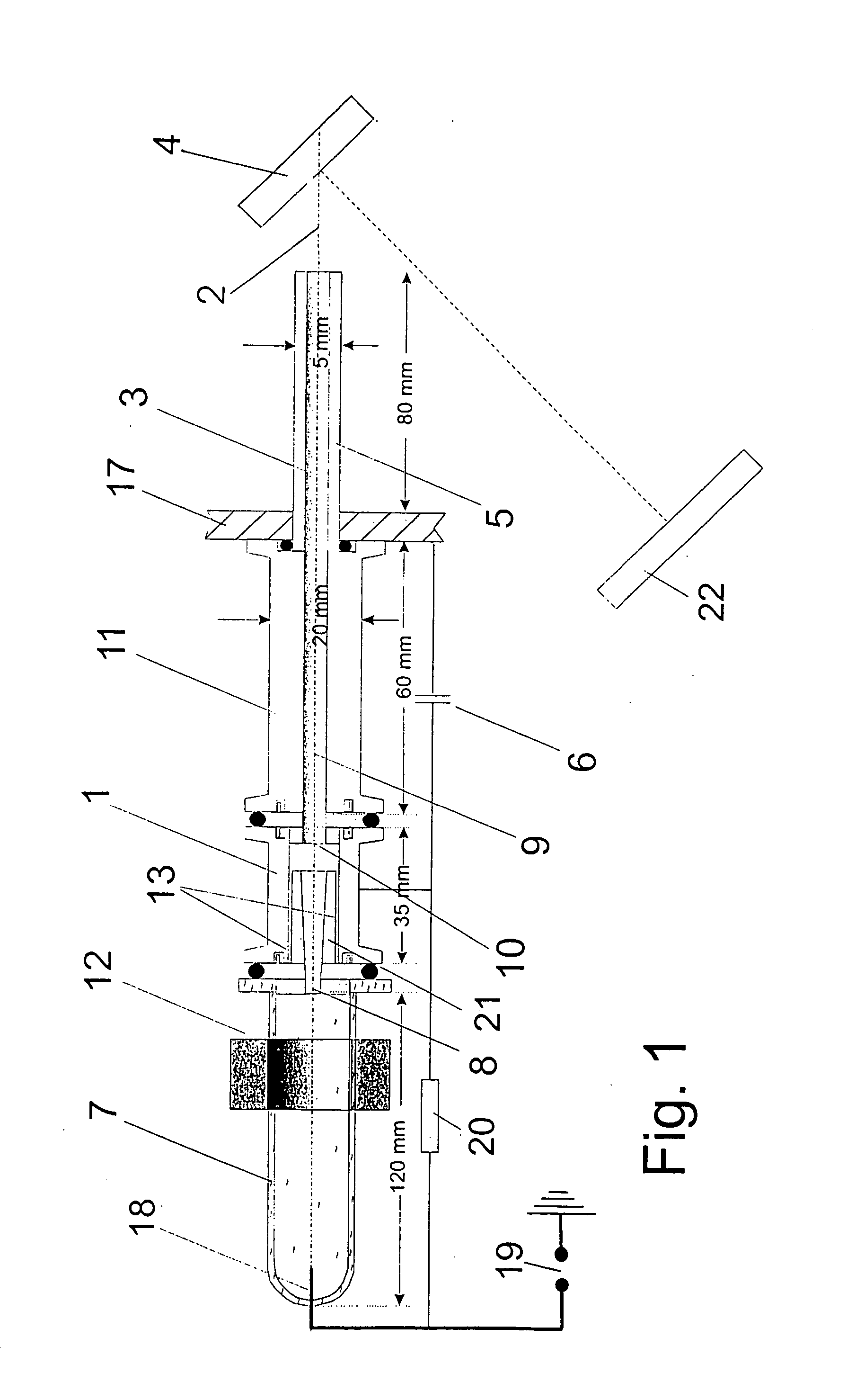
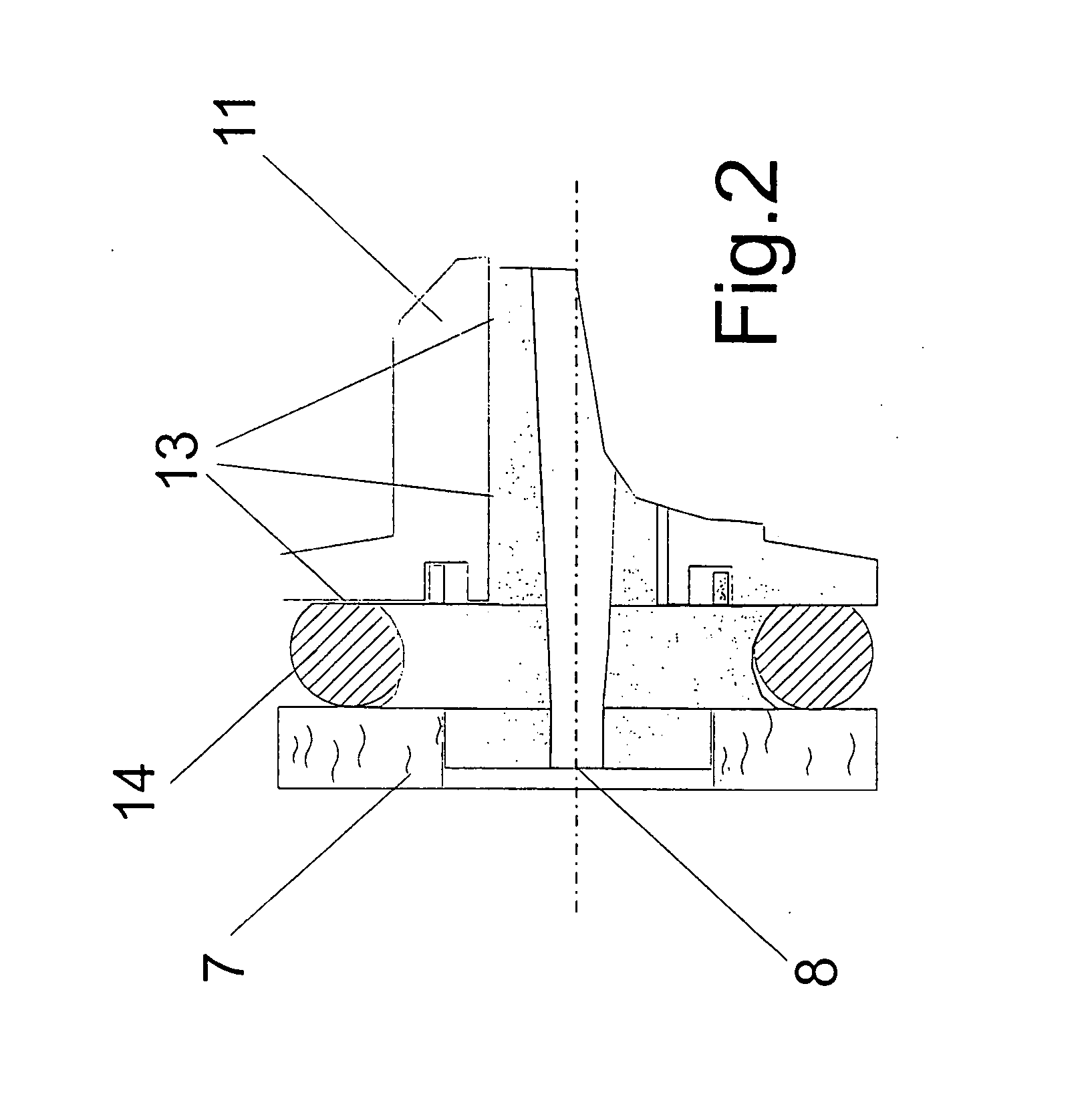
[0034]FIG. 1 is a cross-sectional view along the longitudinal axis of the channel spark source according to the invention. The channel spark source includes a housing 7 for the trigger plasma which housing is test tube shaped and consists of quartz glass. It is flanged to the hollow cathode 1 in a gas-tight manner by way of a support and a rubber ring 14.

[0035] From this coupling location, the conically widening sleeve 21 extends concentrically into the interior of the hollow cathode 1. Between the hollow cathode 1 and the sleeve 2, there is an annular gap 13. The hollow cathode 1 and the sleeve 21 consist of metal. The sleeve 21 ends within the hollow cathode 1. There is still a space at the end of the sleeve 21 with the open diameter of the hollow cathode 1.

[0036] At the exit of the hollow cathode 1, there is the channel spark body 11 which forms part of the channel spark tube 9 having an inner wall 3 and is flanged to the hollow cathode 1 like the housing 7 for the trigger plas...


PUM

PropertyMeasurementUnit
pulse frequencyaaaaaaaaaa
poweraaaaaaaaaa
pressureaaaaaaaaaa

Abstract

In a channel spark source triggered by gas discharge for generating a stable focused electron beam, a gas supply for a hollow cathode thereof is provided which generates in the hollow cathode a pressure differential so that the multiplication of charge carriers in a trigger plasma of a trigger plasma source connected to the hollow cathode provides for a reliable gas discharge and the formation of a stable electron beam which exits the arrangement and which does not damage the internal passages of the arrangement.

Description

[0001] This is a Continuation-In-Part Application of international application PCT / EP03 / 00719 filed Jan. 24, 2003 and claiming the priority of German application 102 07 835.1 filed Feb. 25, 2002. BACKGROUND OF THE INVENTION [0002] The invention relates to a channel spark source for generating a stable focused electron beam comprising, in a co-axial arrangement, a dielectric tube, in which a trigger plasma is generated, and, adjacent thereto, a hollow cathode, a dielectric channel spark body ending at an anode with a central passage, a dielectric tube in alignment with the channel spark body, a condenser connected as an electric energy storage device to the anode and the cathode, an electrode connected by way of a spark gap to a reference potential and an electric resistance bridging the electrode and the hollow cathode. The arrangement corresponds in principle to the arrangement as described in German publication 42 08 764. [0003] The life of the channel spark tube described in DE. ...

Claims


Application Information

Patent Timeline
Patent Type & Authority Applications(United States)
IPC IPC(8): H01J1/02H01J3/02C23C14/30H01J37/077H05H1/24
CPCH01J1/025H05H1/52H01J3/025
Inventor SCHULTEISS, CHRISTOPHBUTH, LOTHAR-HEINZ-OTTO
Owner KERNFORSCHUNGSZENTRUM KARLSRUHE GMBH
Why Eureka
Try Eureka