Fluid control device and method of making it

Inactive Publication Date: 2005-01-27
CONTROL COMPONENTS INC
View PDF4 Cites 27 Cited by
  • Summary
  • Abstract
  • Description
  • Claims
  • Application Information

AI Technical Summary

Benefits of technology

[0018] The method utilized in fabricating the rigid annular valve structure allows for a high degree of process repeatability such that intricately shaped features with tight tolerances may be easily produced. The green state discs are formed with fairly intricate disc passages. The disc passages collectively define a multiplicity of substantially radial device passageways of the rigid annular valve structure. The device passageways each define a plurality of substantially right angle turns for reducing the velocity of fluid flowing through the rigid annular valve structure.
[0019] The present invention provides a fluid control device comprising a valve housing constructed and arranged for the flow

Problems solved by technology

However, a significant drawback to the use of tungsten carbide is the difficulty in machining components made of tungsten carbide due to its extreme hardness.
After sintering, tungsten carbide components can only be machined by diamond-grit grinding devices.
A substantial cost in utilizing individual discs made of tungsten carbide is the necessity to grind them flat

Method used


Image

  • Fluid control device and method of making it
  • Fluid control device and method of making it
  • Fluid control device and method of making it

Examples


Embodiment Construction

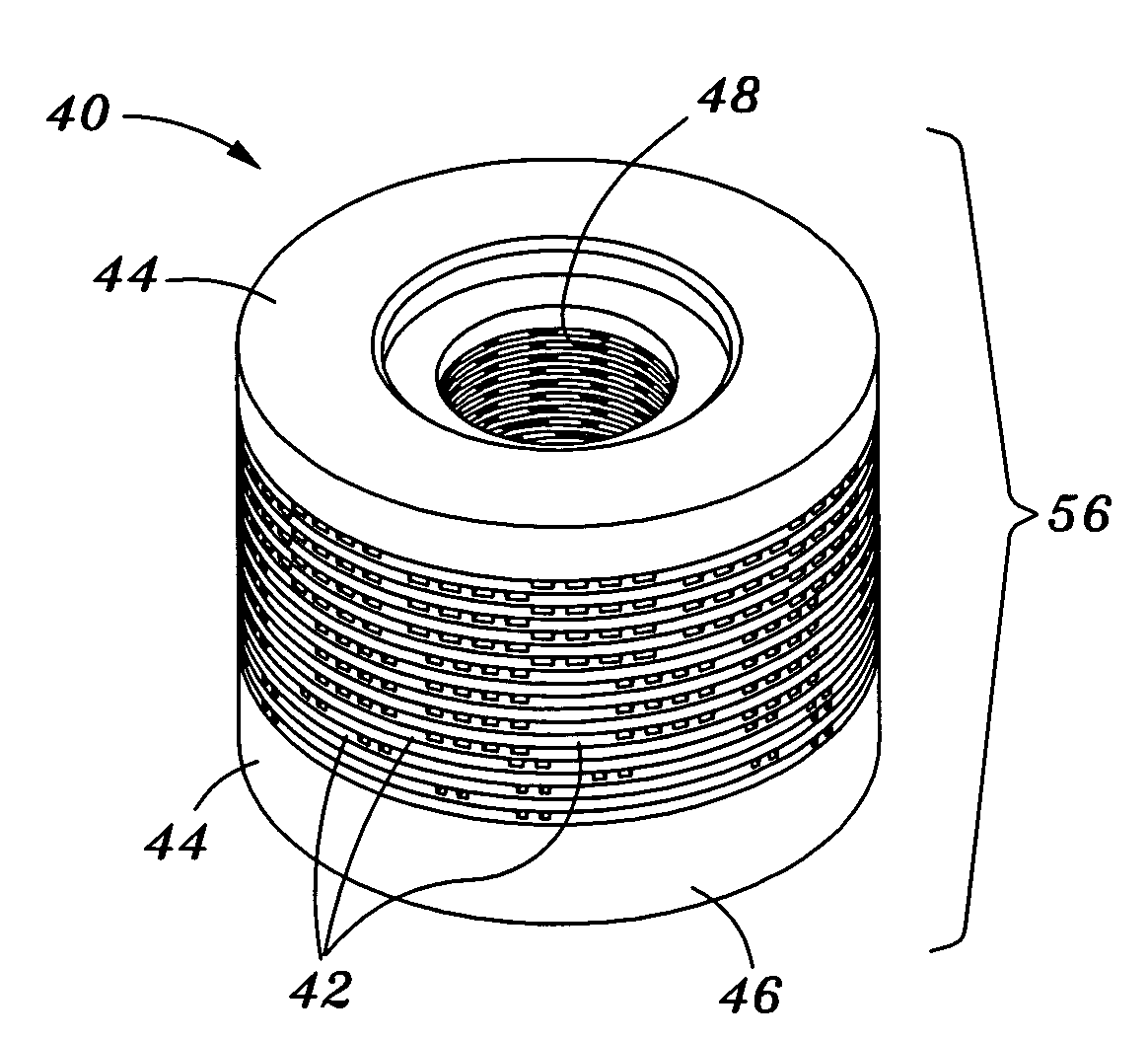
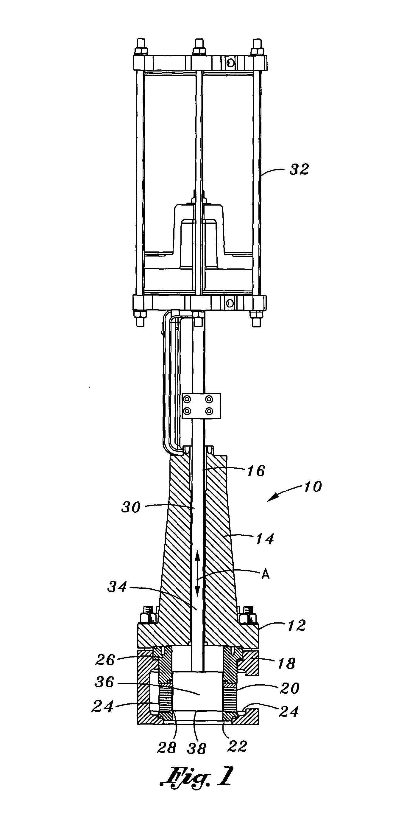
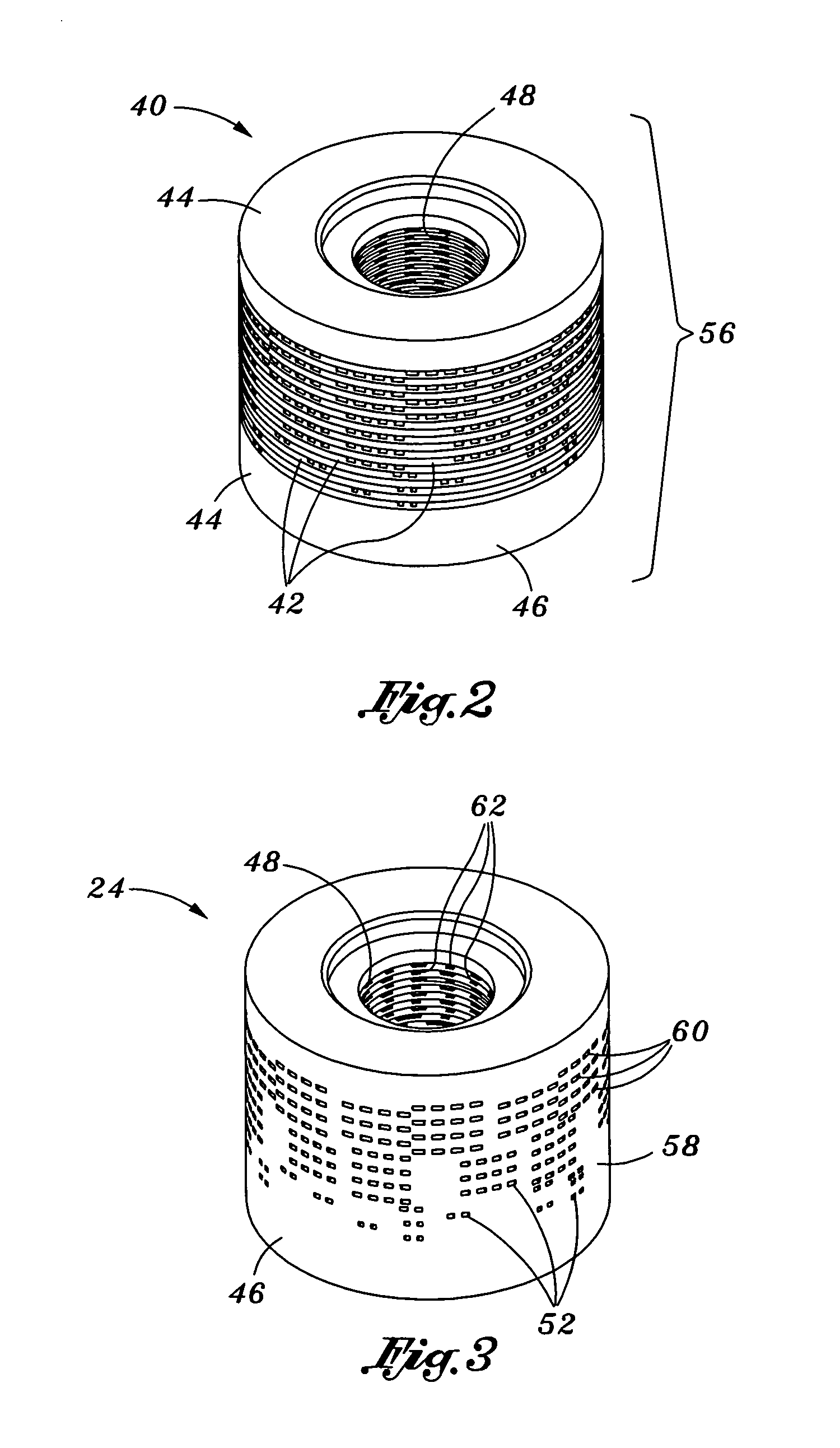
[0035] Referring now to the drawings wherein the showings are for purposes of illustrating the present invention and not for purposes of limiting the same, FIG. 1 illustrates a valve assembly 10 in which the rigid annular valve structure 24 of the present invention may be employed. As will be explained in more detail below, the rigid annular valve structure 24 provides a labyrinth of turns for fluid as it flows through device passageways 52 formed therein. The labyrinth of turns provides resistance to flow in order to limit the velocity of the fluid. The rigid annular valve structure 24 of the present invention provides advantages over similar devices of the prior art due in part to the manner in which the rigid annular valve structure 24 is formed.

[0036] More specifically, in prior art practices, the disc passages 54 are formed in the individual green state discs 42 by electrical discharge machining, punching, laser cutting or casting. The individual green state discs 42 are then ...


PUM


Abstract

Disclosed is a rigid annular valve structure comprised of individual green state discs having partial or complete passages formed therein. The series of green state discs are assembled in an axially aligned stack such that the partial passages of adjacent ones of the green state discs cooperate to collectively define a plurality of substantially radial device passageways for fluid flowing therethrough. The disc passages are formed in the discs prior to the assembly into the stack. The assembled green state discs are heated as a unit in order to simultaneously harden the individual green state discs and to fuse the individual green state discs together to form the rigid annular valve structure. After heating, the rigid annular valve structure may be machined to define interior and exterior peripheries and end faces such that the rigid annular valve structure is suitable for use in a valve assembly.

Description

CROSS-REFERENCE TO RELATED APPLICATIONS [0001] (Not Applicable) STATEMENT RE: FEDERALLY SPONSORED RESEARCH / DEVELOPMENT [0002] (Not Applicable) BACKGROUND OF THE INVENTION [0003] The present invention relates to fluid control devices and, more particularly, to a rigid annular valve structure formed by sintering and fusing together a stack of individual green state discs having discs passages. Disc passages formed in the green state discs cooperate to collectively define a multiplicity of radially extending device passageways. The device passageways each define a plurality of substantially right angle turns for reducing the velocity of fluid flowing through the rigid annular valve structure. [0004] The type of fluid control device herein contemplated is disclosed in commonly owned U.S. Pat. No. 5,687,763. The '763 patent discloses a fluid control device including a valve housing with a rigid annular valve structure disposed therein. An axially movable valve plug is slidably mounted in...

Claims


Application Information

Patent Timeline
IPC IPC(8): F16K47/08
CPCF16K47/08Y10T137/86734
Inventor STEINKE, JOSEPH H.COCKBILL, KIM
Owner CONTROL COMPONENTS INC
Why Eureka
Try Eureka