
Microwave electron cyclotron resonance plasma chemistry gas phase sedimentation device

A technology of chemical vapor deposition and microwave electron cyclotron, which is applied in the direction of gaseous chemical plating, metal material coating technology, coating, etc., can solve the problem that the wafer processing area and uniformity cannot be satisfied, and there is no batch scale production, wafer processing Small area and other problems, to achieve the effect of enhancing automation and production efficiency, improving process stability and repeatability, and good uniformity

Inactive Publication Date: 2008-03-19
XIDIAN UNIV
View PDF0 Cites 19 Cited by
  • Summary
  • Abstract
  • Description
  • Claims
  • Application Information

AI Technical Summary

Problems solved by technology

ECRCVD equipment provided by well-known foreign ECR equipment manufacturers, taking NEXX Systems’ product Cirrus300 as an example, the plasma density can reach 5×10 11 cm -3 ; The ion energy is about 10-20eV; the microwave source frequency is 2.45GHz, and the power is adjustable from 0 to 1.2 kW; the process equipment system adopts a microcomputer control mode, and the process system has a high degree of automation; the deposition rate can reach about 100nm / min; but The disadvantage of this equipment is that it adopts electromagnetic coil magnetic field, which has high energy consumption and high cost, and the processing area and uniformity of the wafer cannot meet the requirements of current microelectronics technology.
Most domestic microwave ECR plasma sources adopt the form of coaxial coil ECR magnetic field. The disadvantages are that the equipment structure is complex and bulky; the wafer processing area is small, and the diameter of the processable wafer is limited to 2 to 4 inches; Less than 60nm / min; low degree of automation, mostly manual control, does not have the ability to mass-scale production, and has not yet appeared commercial products for mass production

Method used


Image

  • Microwave electron cyclotron resonance plasma chemistry gas phase sedimentation device
  • Microwave electron cyclotron resonance plasma chemistry gas phase sedimentation device
  • Microwave electron cyclotron resonance plasma chemistry gas phase sedimentation device

Examples


Embodiment Construction

[0036] The present invention will be described in further detail below in conjunction with the accompanying drawings.

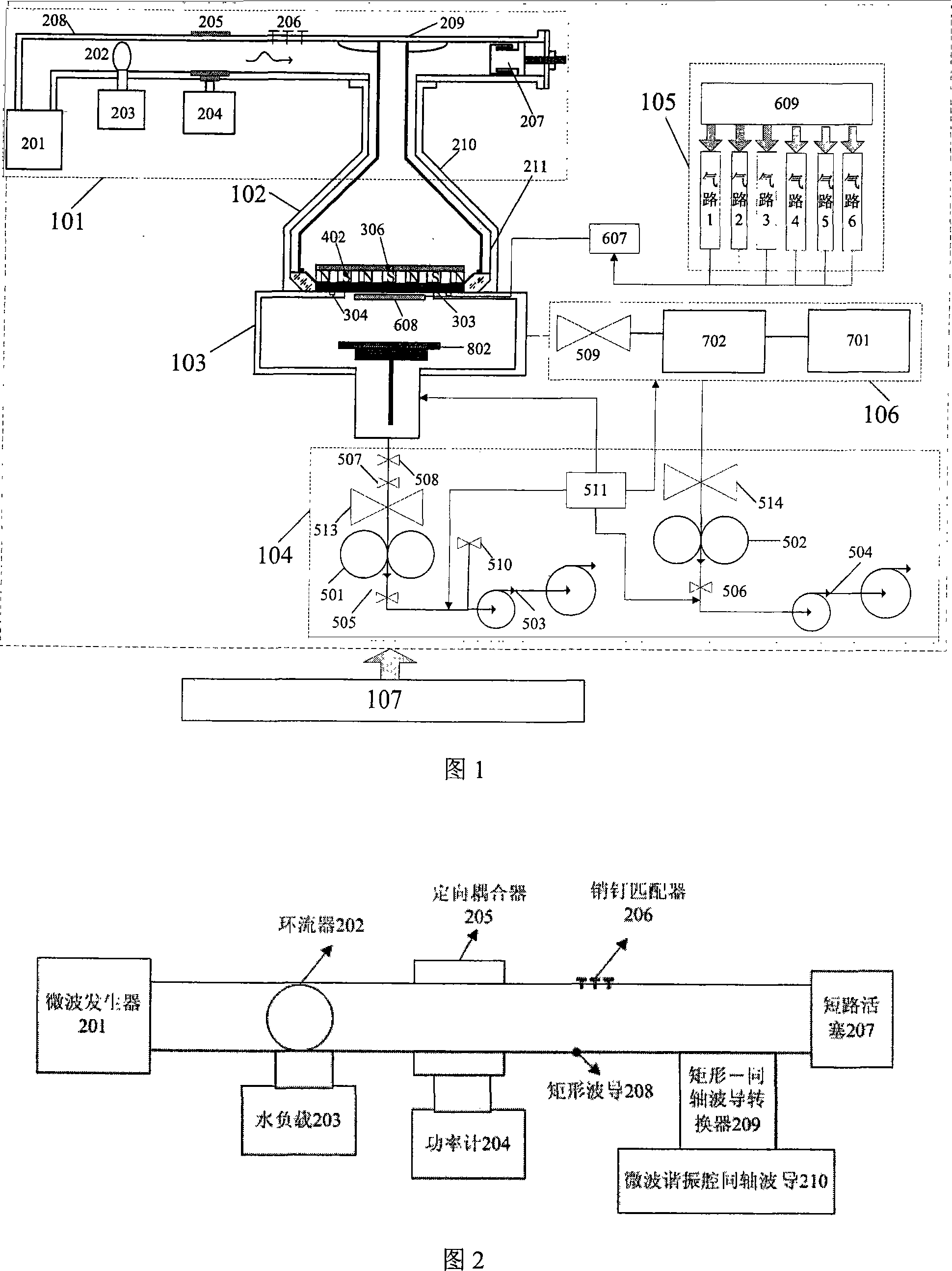
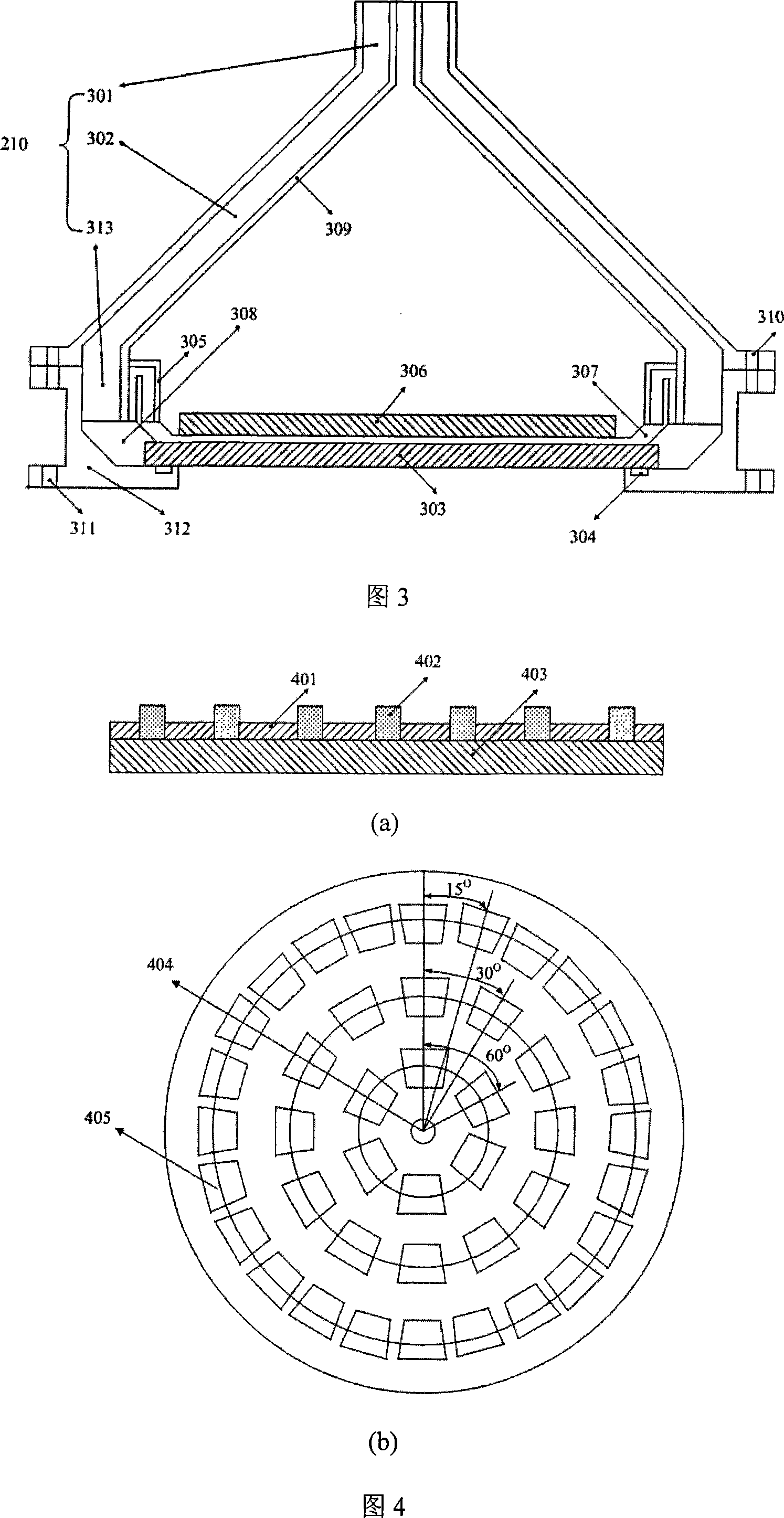
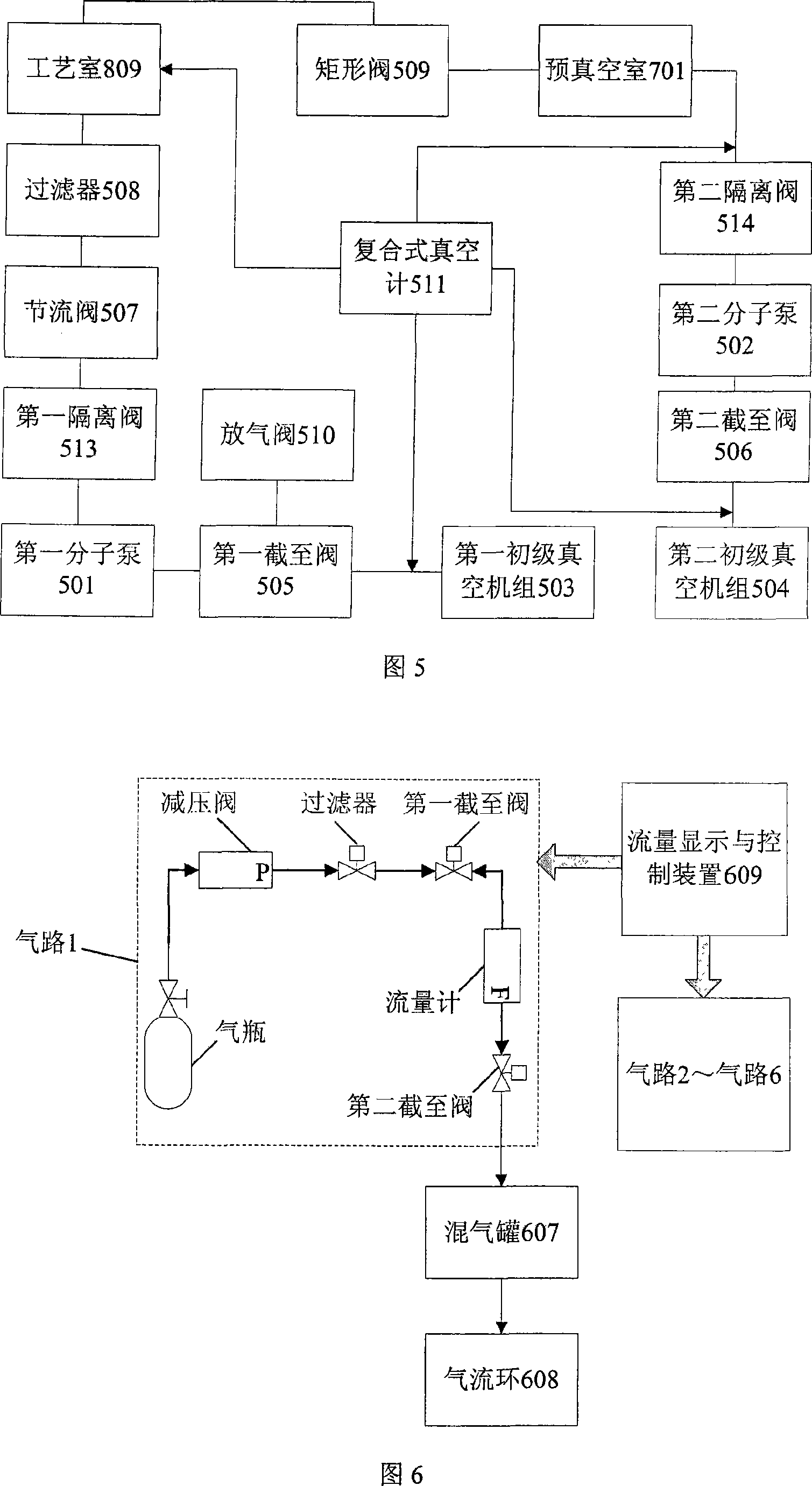
[0037] 1, the microwave electron cyclotron resonance plasma chemical vapor deposition equipment of the present invention includes a microwave power source and transmission system 101, a microwave resonant cavity 102, a process chamber and a sample stage system 103, a vacuum system 104, and a gas path system 105 , automatic film transfer system 106, control system 107. The structure of each system is shown in Figure 2-9.

[0038]Referring to Fig. 2, the microwave power source and transmission system 101 is composed of a microwave generator 201, a circulator 202, a water load 203, a power meter 204, a directional coupler 205, a pin adjuster 206, a short circuit piston 207, a rectangular waveguide 208, a rectangular It is composed of a coaxial waveguide converter 209 and a microwave resonant cavity coaxial waveguide 210 . The connection relationship of each pa...


PUM


Abstract

The present invention discloses microwave electron cyclotron resonance plasma body chemical vapor deposition equipment, which comprises a microwave power source and a transmission system 101, a microwave resonance cavity 102, a coating chamber and a specimen stage system 103, a vacuum system 104, a gas circuit system 105, an automatic sheet transmission system 106, and a controlling system 107, wherein, magnetic field devices 306 which are lined at equal intervals are arranged in the microwave resonance cavity; the specimen stage system is arranged inside the coating chamber; the microwave resonance cavity, the vacuum system, and the automatic sheet transmission system are respectively connected with a coating chamber 809, the microwave power source and the transmission system are connected with the microwave resonance cavity; a controlling software is solidified in the host computer of the controlling system; the working states of the microwave power source and the transmission system, the coating chamber and the specimen stage system, the vacuum system, and the gas circuit system are respectively controlled through interfaces, and thus the deposition technological process of a film is completed. The present invention has the advantages that the big area uniformity is good, the deposition rate is high, the automaticity and the production efficiency are high, the reliability is good, the power loss is small, and the stability and the repeatability are good.

Description

technical field [0001] The invention belongs to the technical field of microelectronic process equipment, and relates to thin film deposition equipment, in particular to a microwave electron cyclotron resonance plasma chemical vapor deposition equipment. Background technique [0002] Microwave Electron Cyclotron Resonance Plasma Chemical Vapor Deposition (ECCVD) technology is one of the important technical foundations of deep submicron microfabrication technology. Electron cyclotron resonance ECR means that when the input microwave frequency ω is equal to the electron cyclotron frequency ω ce Resonance occurs when microwave energy is coupled to electrons, and the energy-gained electrons ionize neutral gas molecules to generate a discharge. By adjusting the magnetic field, the resonance condition is reached in a certain area of ​​the discharge chamber, which is called the ECR area. When the microwave frequency is 2.45GHz, the magnetic induction intensity B=0.0875T of electr...

Claims


Application Information

Patent Timeline
Patent Type & Authority Applications(China)
IPC IPC(8): C23C16/511C23C16/52
Inventor 杨银堂汪家友付俊兴刘毅周端俞书乐陈光族孙青
Owner XIDIAN UNIV
Learn More