
Reactive deposition for electrochemical cell production

Inactive Publication Date: 2005-01-27
NANOGRAM
View PDF73 Cites 122 Cited by
  • Summary
  • Abstract
  • Description
  • Claims
  • Application Information

AI Technical Summary

Benefits of technology

"The invention is about methods for making components for electrochemical cells, such as fuel cells. The methods involve depositing layers of materials onto a substrate using a process called sequential reactive deposition. The layers can include electrically conductive materials, polymers that can conduct ions, or catalyst materials for fuel cells. The methods can also involve coating a rod-shaped substrate with a polymer membrane, or adding a polymer coating to a powder coating for a more uniform distribution. The invention also includes methods for making electrical interconnects and fuel cell components by contacting a cell assembly with a solvent to dissolve a soluble material and form reactant flow channels to an electrode. Overall, the invention provides new ways to make components for electrochemical cells with improved performance."

Problems solved by technology

Particular fuel cell designs introduce specific challenges in material performances.

Method used


Image

  • Reactive deposition for electrochemical cell production
  • Reactive deposition for electrochemical cell production
  • Reactive deposition for electrochemical cell production

Examples


example 1

Laser Pyrolysis Synthesis of Relevant Powders With Aerosol Precursors

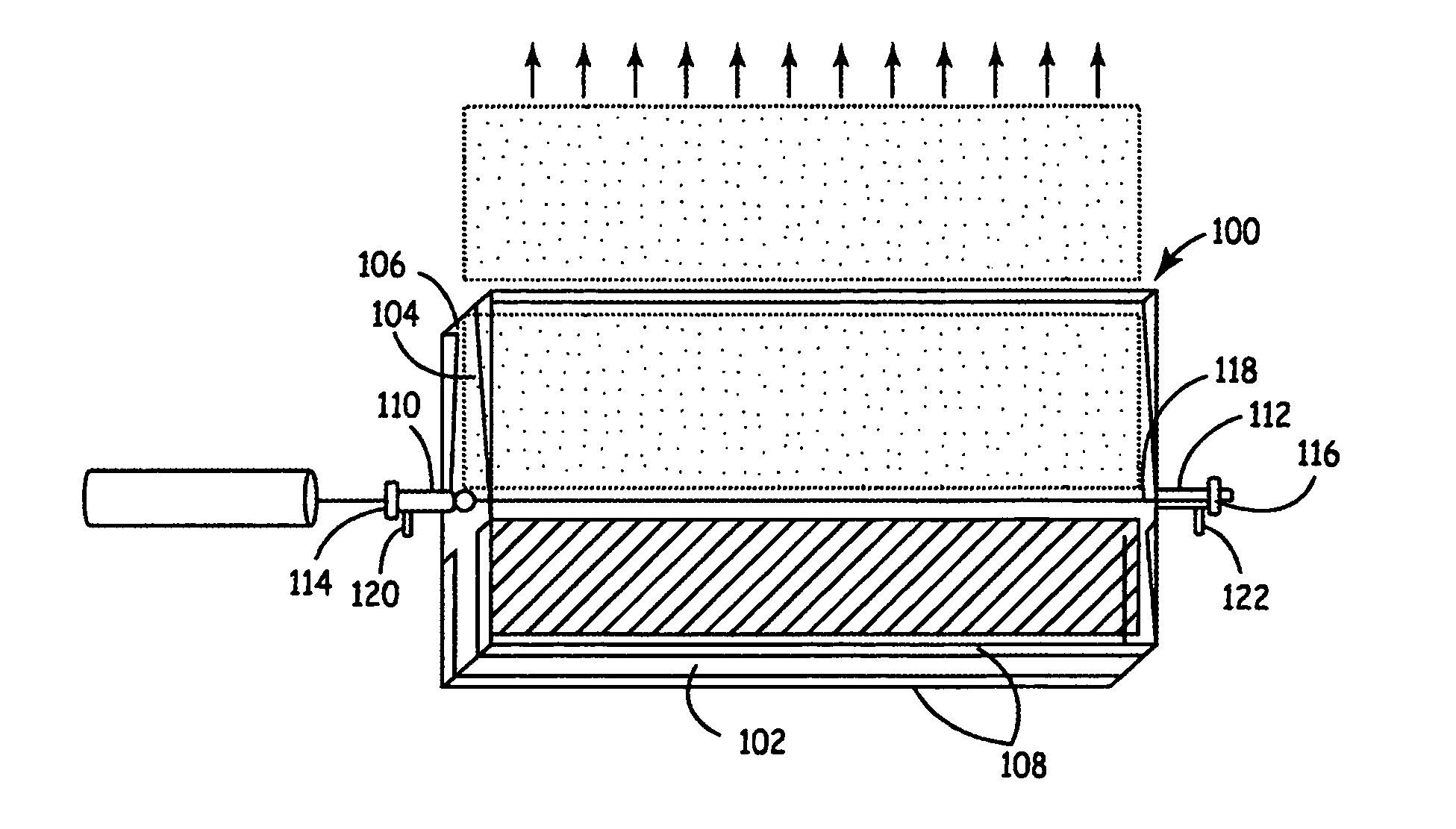
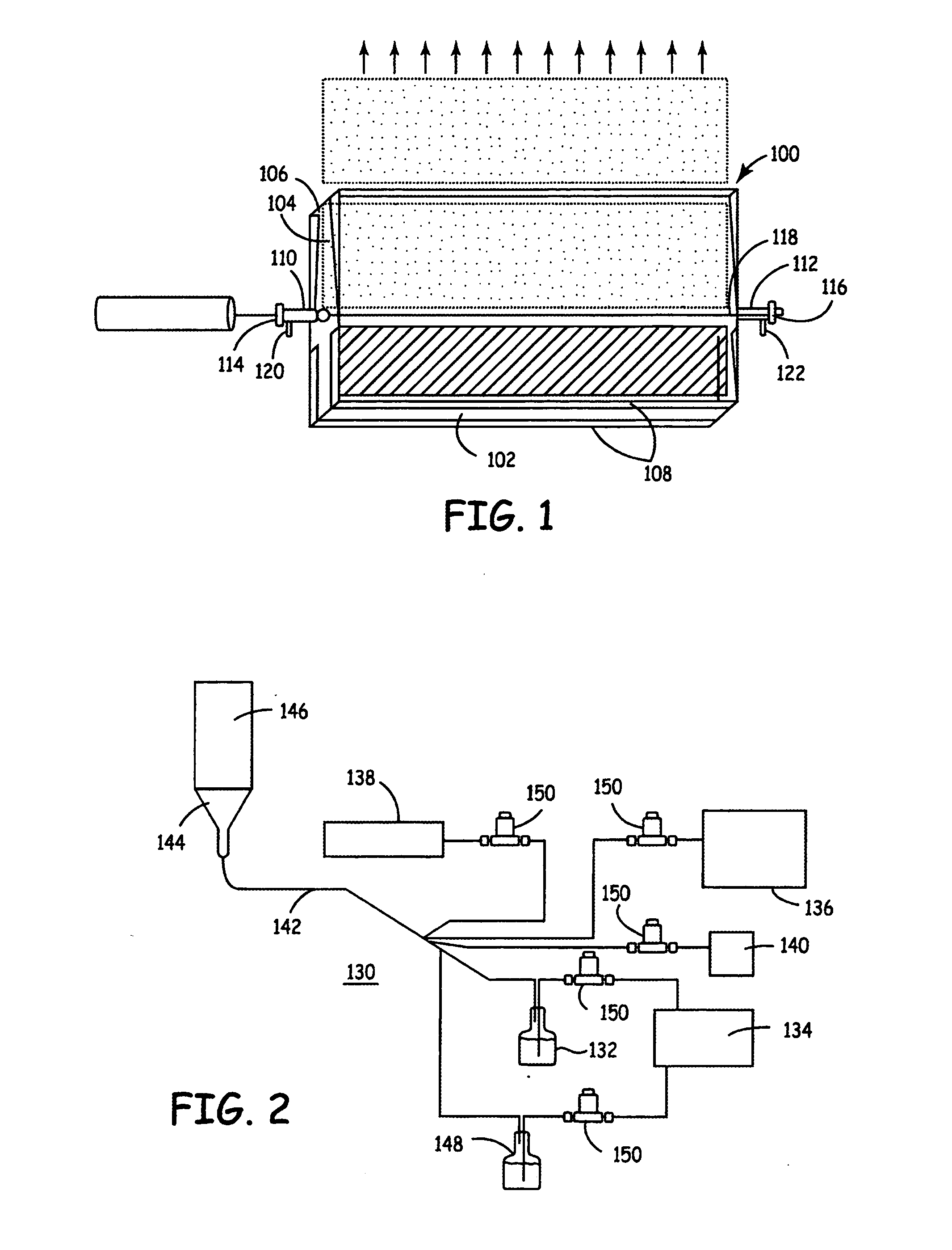
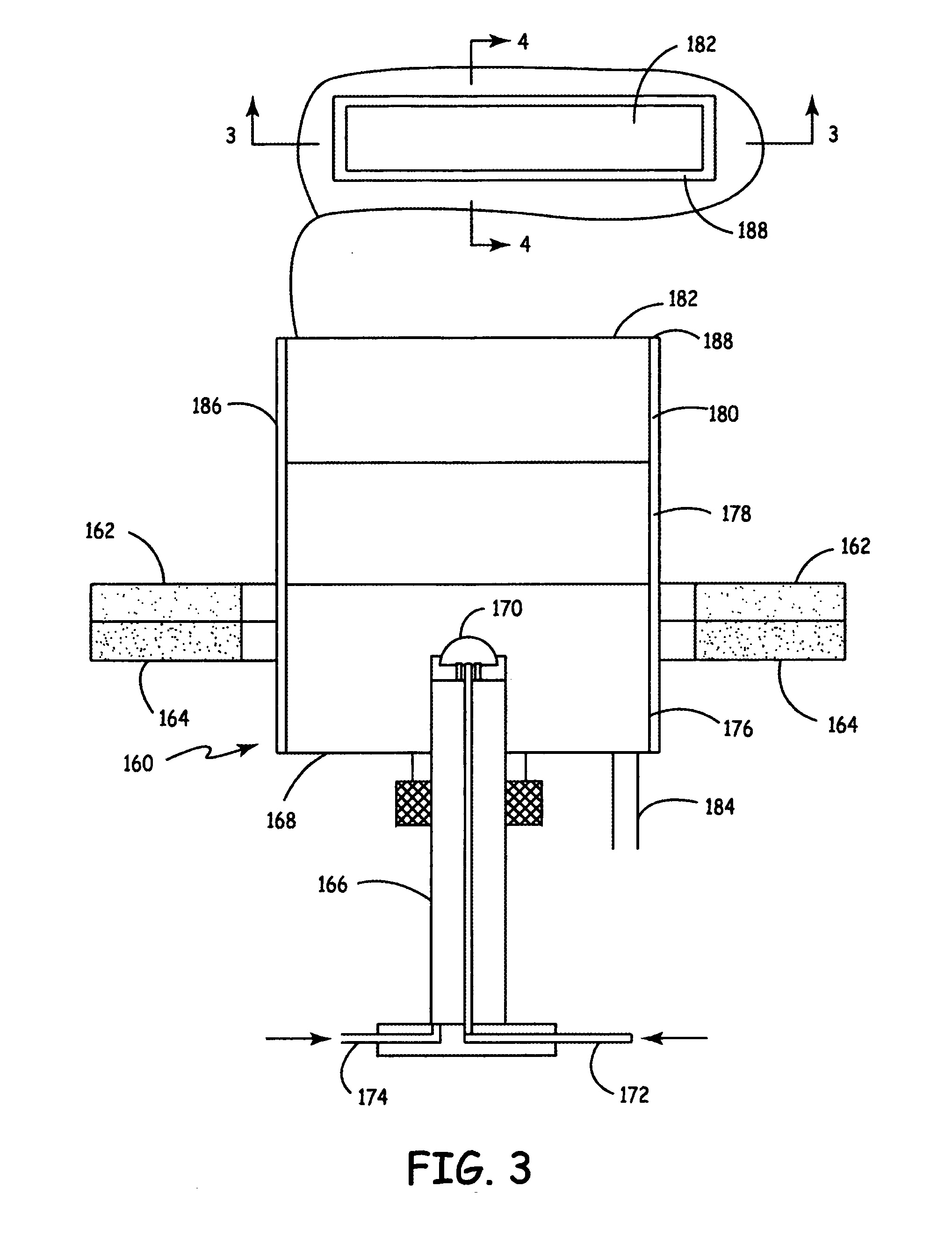
This example demonstrates the synthesis of lithium nickel cobalt oxide by laser pyrolysis with an aerosol. Laser pyrolysis was carried out using a reaction chamber essentially as described above with respect to FIGS. 1, 3 and 4.

Lithium nitrate (Li(NO3)) (99%, 1.1 molar), (Ni(NO3)×6H2O) (technical grade, 0.7 molar), and (Co(NO3)×6H2O) (ACS grade, 0.2 molar) precursor was dissolved in deionized water. The aluminum nitrate precursor was obtained from Alfa Aesar, Inc., Ward Hill, Mass. The solution was stirred on a hot plate using a magnetic stirrer. The aqueous metal precursor solutions were carried into the reaction chamber as an aerosol. C2H4 gas was used as a laser absorbing gas, and nitrogen was used as an inert diluent gas. The reactant mixture containing the metal precursors, N2, O2 and C2H4 was introduced into the reactant nozzle for injection into the reaction chamber. Additional parameters of the laser py...

example 2

This example demonstrates the synthesis of aluminum doped lithium manganese oxides and LiAlO2 by laser pyrolysis with an aerosol. Laser pyrolysis was carried out using a reaction chamber essentially as described above with respect to FIGS. 1, 3 and 4.

Lithium nitrate (Li(NO3)) (99%, 2.3 molar or 2.6 M), (Mn(NO3) solution) (50 w / w, 2.3 molar or 1.9 M), and (Al(NO3)×9H2O) (99.999%, 2.3 molar or 0.1 M) precursor was dissolved in deionized water. The aluminum nitrate precursor was obtained from Alfa Aesar, Inc., Ward Hill, Mass. The solution was stirred on a hot plate using a magnetic stirrer. The aqueous metal precursor solutions were carried into the reaction chamber as an aerosol. C2H4 gas was used as a laser absorbing gas, and nitrogen was used as an inert diluent gas. The reactant mixture containing the metal precursors, N2, O2 and C2H4 was introduced into the reactant nozzle for injection into the reaction chamber. Additional parameters of the laser pyrolysis synthesis relating ...


PUM

PropertyMeasurementUnit
temperaturesaaaaaaaaaa

Abstract

Light reactive deposition can be adapted effectively for the deposition of one or more electrochemical cell components. In particular, electrodes, electrolytes, electrical interconnects can be deposited form a reactive flow. In some embodiments, the reactive flow comprises a reactant stream that intersects a light beam to drive a reaction within a light reactive zone to produce product that is deposited on a substrate. The approach is extremely versatile for the production of a range of compositions that are useful in electrochemical cells and fuel cell, in particular. The properties of the materials, including the density and porosity can be adjusted based on the deposition properties and any subsequent processing including, for example, heat treatments.

Description

FIELD OF THE INVENTION This invention relates to approaches for the formation of electrochemical cells, in particular fuel cells. In particular, the invention relates to reactive deposition approaches for the formation of electrochemical cell structures. The invention further relates to improved structures for electrochemical cells. BACKGROUND OF THE INVENTION Electrochemical cells in general involve reduction-oxidation reactions in separated half-cells that are appropriately connected for ionic flow as well as electrical flow across an external circuit. Batteries and fuel cell produce useful work in the form of the electrical flow across a load generated from the reduction-oxidation reactions. In other electrochemical cells, a load is applied to the cell to induce desired chemical reactions at the electrodes to form desired chemical products. Fuel cells differ from batteries in that both the reducing agent and the oxidizing agent can be replenished without dismantling the cell. F...

Claims


Application Information

Patent Timeline
Patent Type & Authority Applications(United States)
IPC IPC(8): C23C16/48H01M4/86H01M4/88H01M4/92H01M8/02H01M8/12H01M8/24
CPCC23C16/403Y02E60/525C23C16/483C23C18/06C23C18/1204C23C18/1216C23C18/1241C23C18/14C23C24/00C23C26/00H01M4/8621H01M4/8885H01M4/9066H01M4/92H01M8/0271H01M8/1213H01M8/1246H01M8/2485H01M2008/1293H01M2300/0082H01M2300/0094Y02E60/521C23C16/405C23C18/143Y02E60/50Y02P70/50C23C16/00C25B9/13H01M8/0273
Inventor HORNE, CRAIG R.MCGOVERN, WILLIAM E.LYNCH, ROBERT B.MOSSO, RONALD J.
Owner NANOGRAM
Learn More