
Production of fine-grained particles

a technology of fine grains and metal oxides, applied in the direction of nickel compounds, lanthanide oxides/hydroxides, cobalt carbonyls, etc., can solve the problems of difficult uniform dispersion of different elements at the ultra-fine scale required for nanometre-sized grains, and the reported process used to achieve fine grain size is very expensive, so as to achieve a wide distribution of pore sizes and large specific surface areas

Inactive Publication Date: 2005-02-03
VERY SMALL PARTICLE CO LTD
View PDF11 Cites 29 Cited by
  • Summary
  • Abstract
  • Description
  • Claims
  • Application Information

AI Technical Summary

Benefits of technology

[0094] The heating step results in the formation of the metal oxide and the pore structure of the particles. Unlike prior art processes for producing metal oxides, the method of the present invention only requires a relatively low applied temperature. Indeed, applied temperatures of less than about 300° C. have been found to be suitable in experimental work conducted to date. Preferably, the maximum applied temperature reached in step (c) does not exceed about 600° C., more preferably about 450° C., most preferably about 300° C. The present inventors believe that the process of the present invention may involve localised exothermic reactions occurring, which could lead to highly localised temperatures. However, it remains a significant advantage of the present invention that the applied temperature is relatively low compared to prior art processes known to the inventors.
[0095] The heating step may involve a rapid heating to the maximum desired temperature, or it may involve a much more closely controlled heat treatment regime. For example, the heating step may involve heating to a drying temperature (generally below the boiling temperature of the mixture) to dry the mixture, following by a slow ramp up to the maximum applied temperature, or followed by a series of incremental increases to intermediate temperatures before ultimately reaching the maximum applied temperature. The duration of the heating step may vary widely, with a preferred time in step (c) being from 15 minutes to 24 hours, more preferably 15 minutes to 2 hours even more preferably 15 minutes to 1 hour. It will be appreciated that step (c) is intended to encompass all heating profiles that result in the formation of particles of metal oxide.
[0096] The metal oxide particles produced by preferred embodiments of the method have nano-sized grains. Preferably, the grain size falls within the range of 1-50 nm, more preferably 1-20 nm, even more preferably 2-10 nm, most preferably 2-8 nm.
[0097] The grain size was determined by examining a sample of the particles using TEM (transmission electron microscopy), visually evaluating the grain size and calculating an average grain size therefrom. The particles may have varying particle size due to the very fine grains aggregating or cohering together. The particle size may vary from the nanometre range up to the micrometre range or even larger. The particles may have large specific surface areas (for the particular metal oxide, when compared with prior art processes for making those particles) and exhibit a broad distribution of pore sizes.
[0098] The present invention also encompasses metal oxide particles. In a second aspect, the present invention provides metal oxide particles characterised in that the particles have a grain size substantially in the range from 1 to 50 nm.
[0099] Preferably, the grain size falls within the range of 1 to 20 nm more preferably 2 nm to 10 nm, more preferably 2 nm to 8 nm.

Problems solved by technology

However, the ability to economically produce useful metal oxide materials with nanometre-sized grains has proven to be a major challenge to materials science.
This is because as the number of different elements in an oxide increases, it becomes more difficult to uniformly disperse the different elements at the ultra-fine scales required for nanometre-sized grains.
The reported processes used to achieve fine grain size are very expensive, have low yields and can be difficult to scale up.
Many of the fine grained materials that have been produced do not display particularly high surface areas, indicating poor packing of grains.
To achieve grain sizes of a few nanometres in diameter requires relatively long processing times (several hours for small batches).
Another main drawback of the method is that the milled material is prone to severe contamination from the milling media.
Formation of stable intermediates also has to be avoided since the transformation to the final phase pure material might become nearly impossible in that case.
The disadvantages of sol-gel methods are that the precursors can be expensive, careful control of the hydrolysis-condensation reactions is required, and the reactions can be slow.
A major problem with this technique is that the yield (wt product / wt solution) is small.
Many of the aqueous phase reactions themselves already have low yields, therefore a further significant reduction in yield is very undesirable.
This can be very difficult for nanosised particles surrounded by surfactant, since these particles can remain suspended in solution, and are very difficult to filter due to their small size.
Another serious disadvantage is that reaction times can be quite long.
These aspects together would greatly increase the size, complexity and cost of any commercial production facility.
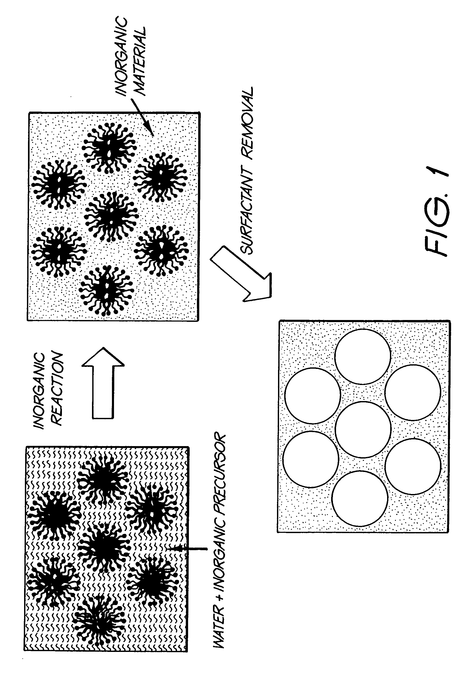
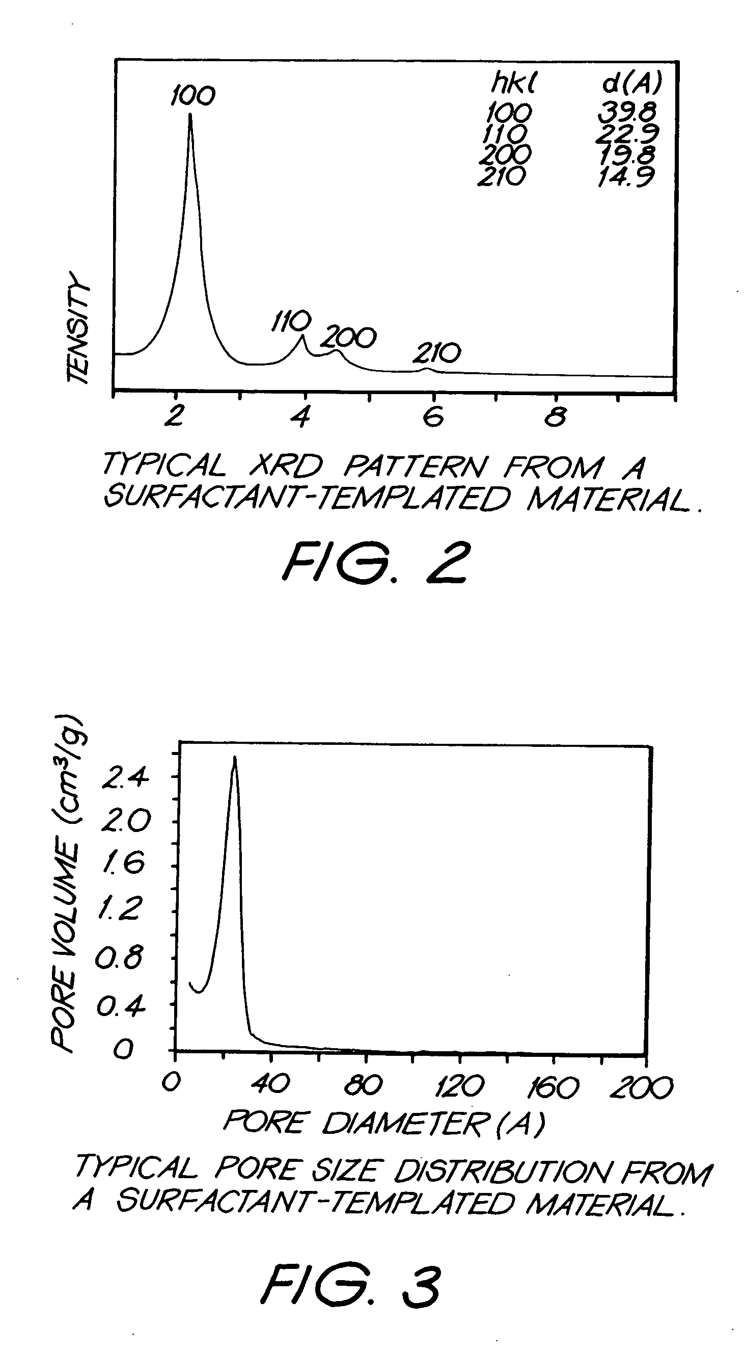
Since the diameter of the surfactant micelles can be extremely small, the pore sizes that can be created using the method are also extremely small, and this leads to very high surface areas in the final product.
A major drawback of most surfactant-templated materials is that normally the inorganic material is not highly crystalline.
The difficulties in producing highly crystalline materials derive from restrictions imposed by the very nature of surfactant templating.
These restrictions greatly limit the types of reactions that can be used to form inorganic material.
Long reaction times greatly add to the expense and inconvenience of processing at a practical scale.
If the inorganic phase forms too rapidly, then large inorganic precipitates that do not contain surfactant will form and drop out of solution.
Clearly this would result in a non-porous structure.
As discussed previously this is a major limitation of most surfactant-templated materials.
It is possible to increase the order in the inorganic material by heat treating at high temperatures, but almost all attempts to do this have resulted in collapse of the pore structure prior to crystallisation.
However the amount of crystallinity was still small, and the inorganic phase consisted of very small crystalline regions surrounded by amorphous inorganic material.
Crystallinity is difficult to obtain.
Reaction times are lengthy because significant time is required to form the surfactant-inorganic structure in solution.
For some mixtures, cooling will result in gel formation.

Method used


Image

  • Production of fine-grained particles
  • Production of fine-grained particles
  • Production of fine-grained particles

Examples


example 1

Production of CeO2

[0107] In order to demonstrate the method of the present invention, particles of CeO2 were produced. The following procedure was used:

[0108] Step 1: A cerium nitrate solution containing 2.5 moles / litre cerium nitrate was prepared.

[0109] Step 2: 16 g Brij 56 surfactant and 20 mls cerium nitrate solution were heated to ˜80° C. At this temperature the surfactant is a liquid. The solution was added slowly to the surfactant liquid while stirring, to create a micellar liquid.

[0110] Step 3: The micellar liquid was cooled to room temperature. During the cooling the liquid transformed to a clear gel.

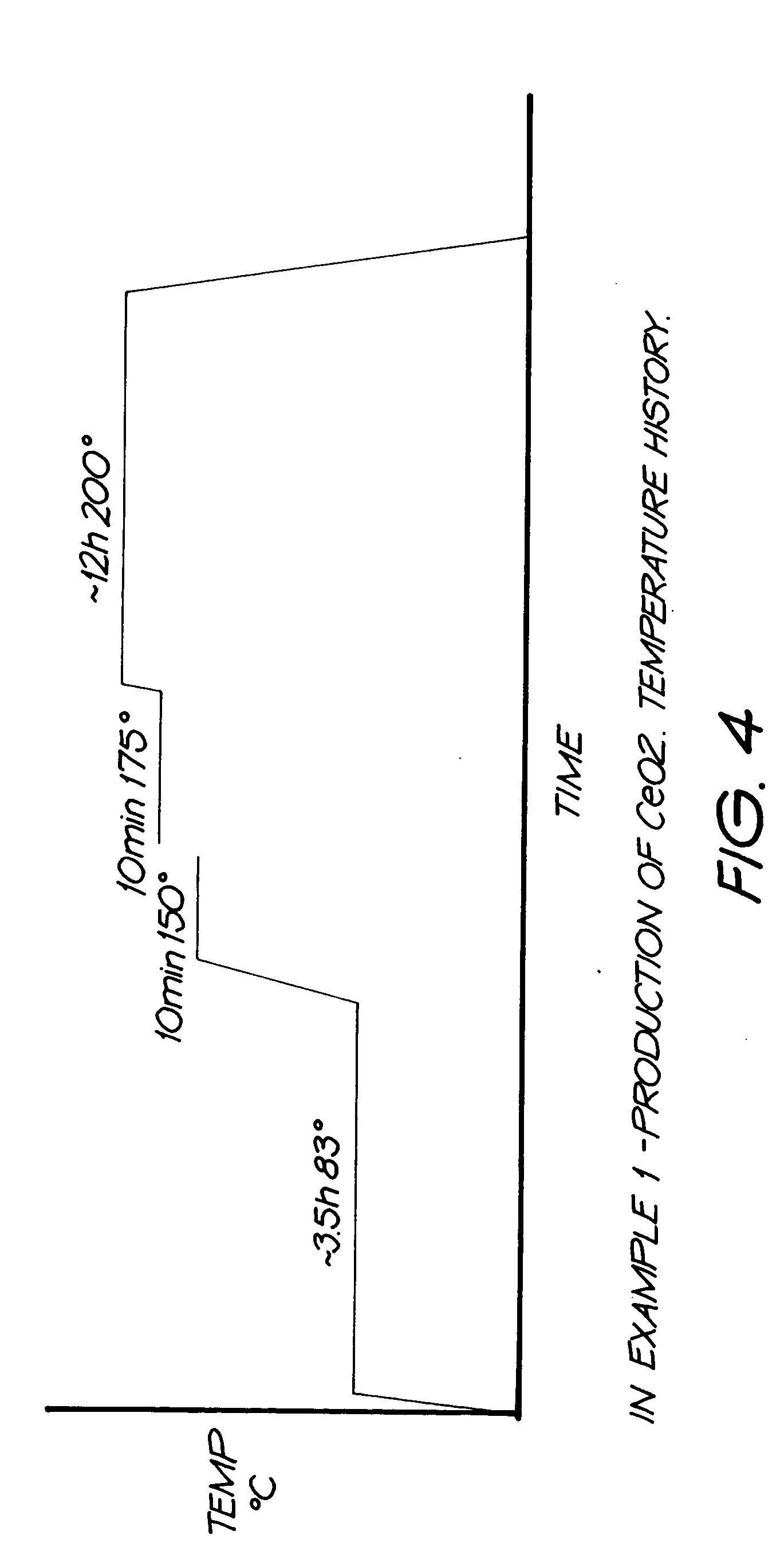
[0111] Step 4: The gel was heat treated according to temperature history presented in FIG. 4. In this example, an extended drying stage at 83° C. was used prior to further heating.

[0112] The resulting CeO2 powder had a surface area of ˜253m2 / g, and was comprised of grains that ranged between ˜2 and ˜8 nm in diameter. Transmission electron microscopy (TEM) suggests that the...

example

Preparation of La0.6Ca0.2Nd0.2Mn0.9Ni0.1O3

[0122] La0.6Ca0.2Nd0.2Mn0.9Ni0.1O3 is used as the cathode material in solid oxide fuel cells. It is also an excellent test material for the present invention because the target ‘lanthanum manganatecrystal structure is extremely sensitive to chemical composition. Even small variations in composition result in the formation of different crystal structures. Therefore, the five different metal elements need to be evenly distributed on an extremely fine scale to produce small grains with the correct crystal structure.

[0123] Using co-precipitation and other conventional processes, previous researchers have had considerable difficulty in obtaining the correct crystal structure because of this sensitivity to composition. Careful co-precipitation, followed by long (10h-48h) heat treatments at high temperatures (800-1000° C.) have been necessary to attain the correct crystal structure in the prior art (variations in chemical composition can be all...


PUM

PropertyMeasurementUnit
grain sizeaaaaaaaaaa

Abstract

Particles of mixed metal oxide include at least two metal species. The particles have a grain size within the range of 1-100 nm. The particles are substantially crystalline. The particles contain only small or negligible amounts of amorphous material. The at least two metal species are uniformly dispersed in the particles.

Description

FIELD OF THE INVENTION [0001] The present invention relates to very fine-grained particulate material and to methods for producing such very fine-grained particulate material. In preferred aspects, the present invention relates to oxide materials of very fine-grained particulate material and to methods for producing such material. Most suitably, the particulate material has grain sizes in the nanometre scale. BACKGROUND OF THE INVENTION [0002] Metal oxides are used in a wide range of applications. For example, metal oxides can be used in: [0003] solid oxide fuel cells (in the cathode, anode, electrolyte and interconnect); [0004] catalytic materials (automobile exhausts, emission control, chemical synthesis, oil refinery, waste management); [0005] magnetic materials; [0006] superconducting ceramics; [0007] optoelectric materials; [0008] sensors (eg gas sensors, fuel control for engines); [0009] structural ceramics (eg artificial joints). [0010] Conventional metal oxides typically hav...

Claims


Application Information

Patent Timeline
Patent Type & Authority Applications(United States)
IPC IPC(8): B82B3/00B01J19/00C01B13/14C01B13/18C01B13/32C01F1/00C01F17/235C01F17/241C01G1/02C01G3/00C01G25/00C01G45/00C01G45/02C01G51/00C01G53/00C01G53/02
CPCB82Y30/00C01P2006/17C01B13/185C01F17/0043C01G1/02C01G3/006C01G25/006C01G25/02C01G45/02C01G45/1242C01G45/1264C01G51/02C01G51/42C01G53/02C01G53/56C01G53/68C01P2002/01C01P2002/52C01P2002/72C01P2004/04C01P2004/50C01P2004/64C01P2006/12C01P2006/14C01P2006/16C01B13/18C01F17/235C01F17/241B82B3/00B82Y40/00
Inventor TALBOT, PETER CADEALARCO, JOSE ANTONIOEDWARDS, GEOFFREY ALAN
Owner VERY SMALL PARTICLE CO LTD
Learn More