Systems and methods for NMR logging

a technology of nmr and logging, applied in the field of nmr measurements, can solve the problems of induced signal decay, present generation of nmr tools, shallow depth of investigation, etc., and achieve the effects of improving the quality of deep nmr measurements, reducing power requirements, and improving the signal-to-noise ratio (snr) results

Active Publication Date: 2005-02-10
HALLIBURTON ENERGY SERVICES INC
View PDF99 Cites 118 Cited by
  • Summary
  • Abstract
  • Description
  • Claims
  • Application Information

AI Technical Summary

Benefits of technology

This application is directed in one aspect to NMR tools capable of conducting NMR measurements in deep sensitive volumes, where borehole fluid effect can be ignored for practical purposes. In another aspect, the application is directed to NMR tools having directional sensitivity. The tool is capable of producing azimuthally symmetric static magnetic field B0 with a low gradient G0, which facilitates greater depths of investigation. In a specific embodiment, NMR measurements can be conducted in a plurality of sensitive volumes ranging from about 20 cm to about 80 cm and beyond from the tool. Shallow volumes may be used to replicate the conventional NMR logging measurements, such as porosity, T1 and T2 relaxation measurements, bound fluid volume, etc. These measurements characterize the pore space, the type and volume of bound fluids and volume available for producible (movable) fluids. Deep volumes enable quantification of hydrocarbon saturation substantially independent of the borehole effects, such as formation invasion by borehole fluids. To this end, the deep measurements may be used to supplement the shallow free-fluid measurements by quantifying the amount of oil and gas present at a distance from the borehole. Taken together, shallow and deep volume measurements may be used as basis for stand-alone formation evaluation, enabling more accurate estimates of porosity, quantification of producible hydrocarbons, for borehole invasion profiling, and others.
In another embodiment, the NMR tool comprises a single, axially polarized magnet assembly having a permanent magnet longitudinally extended, at both poles, with one or more soft-magnetic pole pieces, thus simulating a magnetic monopole in the near regions of the formation. One or both pole pieces may in turn be adjacent to one or more RF antenna assemblies. Each antenna assembly further comprises a (tubular) ferromagnetic core and one or more antenna coils wound around the core. The coils include preferably at least one solenoid coil and at least two orthogonally-placed saddle coils. Each antenna assembly is enclosed into a non-conductive, non-magnetic protective shield. Finally, the entire magnetic assembly may be mounted on a drill collar having mud flow conduit therein to facilitate mud circulation in the borehole.
In a preferred embodiment, the NMR tool is capable of directional NMR detection. In particular, the directional sensitivity of the tool is provided by a unique design of RF transceiver antenna and a novel data processing method. In particular, a solenoid coil is capable of imparting an azimuthally symmetric magnetic field B1. Directionally-sensitive antenna segments, in turn, are capable of detecting NMR signals from different sections of the sensitive volume. The data processing method in a preferred embodiment combines NMR signals detected by the antenna coils to enable analysis of the received NMR signals to determine which regions of formation are characterized by the given NMR response. Such directional NMR detection, combined with conventional accelerometer and magnetometer readings, enables real-time payzone steering during borehole drilling.
In another aspect, this application is directed to a method for optimizing the reception of signals from a deep sensitive volume of the tool with reduced power requirements. The method is based on a novel pulse sequence for NMR relaxation measurements. In particular, by lengthening each refocusing pulse (π) of the standard CPMG pulse sequence and frequency-modulating each pulse, a substantial improvement in signal-to-noise ratio (SNR) results, thus improving the quality of deep NMR measurements. In another aspect, various signal-processing techniques are disclosed suitable to further improve SNR from deep measurements. Additional aspects of the invention(s) in this disclosure will become apparent to those skilled in the art upon reviewing the description in light of the illustrative figures described below.

Problems solved by technology

Due to inhomogeneities in the static magnetic field and irreversible molecular processes, the protons quickly begin to de-phase, which causes the induced signal to decay.
Notwithstanding the numerous advantages of current NMR technology, present generation of NMR tools have one key weakness—shallow depth of investigation—which is typically about 10-20 cm from the tool.
This is a problem because producible formation fluids (e.g., gas, oil, and water) are often displaced in the formation surrounding the borehole by invading borehole fluids (i.e., drilling mud) driven by high borehole pressure.
Because of displacement of the formation fluids, the NMR LWD systems, however, cannot accurately quantify the amounts of producible hydrocarbons (i.e., oil and gas) present in the formation surrounding the borehole—a factor of great significance in predicting producibility of a hydrocarbon reservoir.
The main obstacle to conducting deep NMR measurements is the high gradient G0 of the static magnetic field B0.
However, such investigation depths are still too shallow to enable adequate NMR measurements in regions of the formation unaffected by the invaded formation fluids.
As a result, information gathered by the tool is limited and the quality of its measurements may be compromised.
Moreover, none of the above tools provide directionally sensitive data about the formation, which would facilitate directional drilling capabilities.
It is not possible to suppress the mutual interaction while at the same time maintaining good azimuthal coverage.
Thus, Sezginer et al. require either very narrow antennas, which have low SNR and poor azimuthal coverage or do not disclose a workable system due to the fact that antennas in close proximity are electrically equivalent to coupled tank circuits, which exhibit split resonances.
The prior art does not disclose or suggest a system that obtains directional information from a formation and also is capable of operating at multiple frequencies.

Method used


Image

  • Systems and methods for NMR logging
  • Systems and methods for NMR logging
  • Systems and methods for NMR logging

Examples


first embodiment

Antenna Assembly in the First Embodiment

(1) Yoke

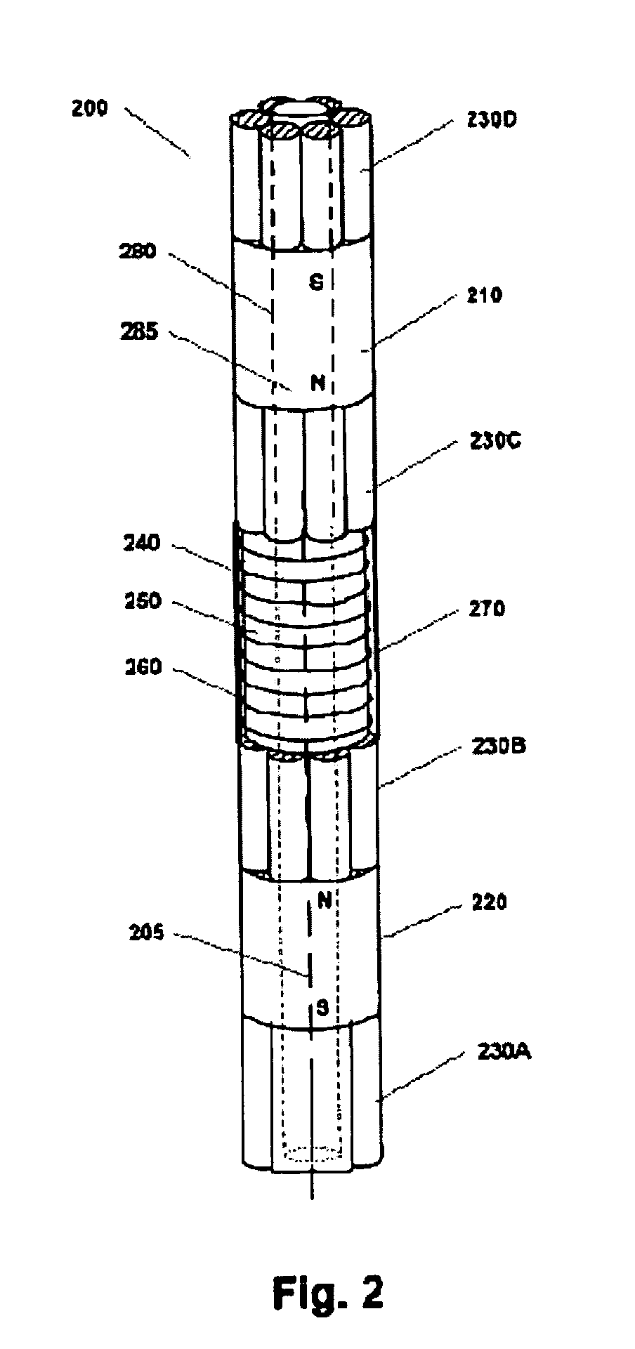
In accordance with a one embodiment, the proximal ends of the inner pole pieces 230 are attached to a yoke (not shown). The yoke may have cylindrical shape with its longitudinal axis aligned in coincidence with the axis of the tool 100. Preferably, pole pieces 230 are not joined rigidly with the yoke, but can move some against each other to provide overall bending flexibility. Because the yoke is interposed between the inner pole pieces of magnets 210 and 220, the entire magnetic assembly is symmetric around the yoke. The length of the yoke is preferably about 80 cm. Thus, the length of the entire magnetic assembly in this embodiment is about 315 cm. In general, the yoke may provide support for RF transceiver antenna 240, as described next. The yoke is preferably made of a mechanically durable soft-magnetic material.

(2) Antenna Core

With reference to FIG. 2, in accordance with a preferred embodiment, magnetic assembly 200 further...


PUM


Abstract

An NMR logging tool for conducting NMR measurements in a plurality of sensitive volumes ranging up to a meter from the tool. The tool comprises a magnetic assembly using one or more permanent magnets and at least one pole piece for extending a magnet pole and shaping the magnetic field to simulate a magnetic monopole in a sensitive volume within the formation. Different embodiments of a segmented antenna enable directional NMR logging. The tool embodiments and methods of their use are suitable for wireline or LWD logging, and can be used for directional drilling.

Description

FIELD OF INVENTION This patent application is directed to nuclear magnetic resonance (NMR) measurements for wireline and logging while drilling (LWD) applications. More specifically, in different aspects the application is directed to NMR systems, methods and applications for deep-looking NMR logging and directional measurement sensitivity. BACKGROUND OF THE INVENTION Well logging is a common practice in the oil and gas industry to evaluate underground formations for the presence and producibility of hydrocarbon reservoirs. Among the most important parameters determined in the process are the depth and thickness of formation layers containing a potential hydrocarbon reservoir, the formation porosity (i.e., the relative amount of void space in the formation), the hydrocarbon saturation (i.e., the relative percentage of hydrocarbons versus water in the pore space), and the permeability (i.e., the ability of the oil, gas, or water to flow out of the formation, into the well and event...

Claims


Application Information

Patent Timeline
Patent Type & Authority Applications(United States)
IPC IPC(8): G01R33/44G01V3/32
CPCG01V3/32G01N24/081
Inventor PRAMMER, MANFRED G.KNIZHNIK, SERGEYMENGER, STEFAN K.GOODMAN, GEORGE D.HARRIS, EDWARD J. IIIDRACK, EARLE
Owner HALLIBURTON ENERGY SERVICES INC
Why Eureka
Try Eureka