
Method and apparatus for a high efficiency ultraviolet radiation source

a radiation source and high-efficiency technology, applied in the direction of electrical equipment, electric discharge lamps, water/sludge/sewage treatment, etc., can solve the problems of high temperature and high uv-c radiation generation, rapid vaporization of filaments, and the inability to extract uv radiation from the end of electrical discharges, so as to improve the overall efficiency of uv sources

Inactive Publication Date: 2005-02-17
ABQ ULTRAVIOLET POLLUTION SOLUTIONS
View PDF20 Cites 13 Cited by
  • Summary
  • Abstract
  • Description
  • Claims
  • Application Information

AI Technical Summary

Benefits of technology

[0012] An ultraviolet radiation (“UV”) source (or lamp) based on capacitively coupled, high-frequency or radiofrequency electric fields is disclosed that creates an efficient, intense UV output. The invention pertains to the method of creating and applying or bonding metallic electrodes to the external portion of the UV source envelope such that high-frequency electrical energy is efficiently coupled to the capacitance and resistance of the source. As used herein, an intense UV source is one that emits substantial amounts of high-energy, shorter wavelength UV as well as, possibly incidentally, wavelengths reaching into the visible and infrared spectrum, in comparison to typical UV sources known today. This method and apparatus allows for efficient production of UV radiation.
[0013] It is another object of the invention to provide a method and apparatus for producing intense UV output while eliminating substantially all electrode erosion.
[0014] It is yet another object of the invention to produce a long-lasting intense UV source, capable of producing >200 W of UV-C per meter length by substantially eliminating the effect of electrode erosion and electrode material redeposition on the transmission of UV through the transmitting envelope.
[0017] Finally, the overall efficiency of the UV source may be improved by material, material thickness, geometry, and / or the material application processes used for the electrodes and the insulating envelope.

Problems solved by technology

Because the erosion of electrodes and the re-deposition of electrode material on the glass envelope are serious lifetime issues, effort has been made to use radio-frequency electric fields or microwaves to drive the lamps.
The limitation is the rapid vaporization of the filament.
However, this concept does not lead to temperatures high enough to generate significant quantities of UV-C radiation.
The practical limitation of this concept is that the UV radiation can only be extracted from the ends of the electrical discharge near one of the electrodes.

Method used


Image

  • Method and apparatus for a high efficiency ultraviolet radiation source
  • Method and apparatus for a high efficiency ultraviolet radiation source
  • Method and apparatus for a high efficiency ultraviolet radiation source

Examples


first embodiment

[0029] The output UV power (as measured by a calibrated UV photometer—Model UVX Radiometer manufactured by UVP) and the UV spectra (as measured by UV spectrometers—EPP2000 Fiber Optic Spectrometer manufactured by StellarNet Inc. and USB2000 manufactured by Ocean Optics Inc.) of the UV source can be varied in several different ways, according to the specific application. An average output power in the UV-C spectrum of greater than 50 W from a 50-cm long xenon-filled lamp in the first embodiment has been observed. Similarly, an average power in the UV-C spectrum of greater than 200 W from a 1.5-m long low-pressure neon / mercury lamp has been observed.

second embodiment

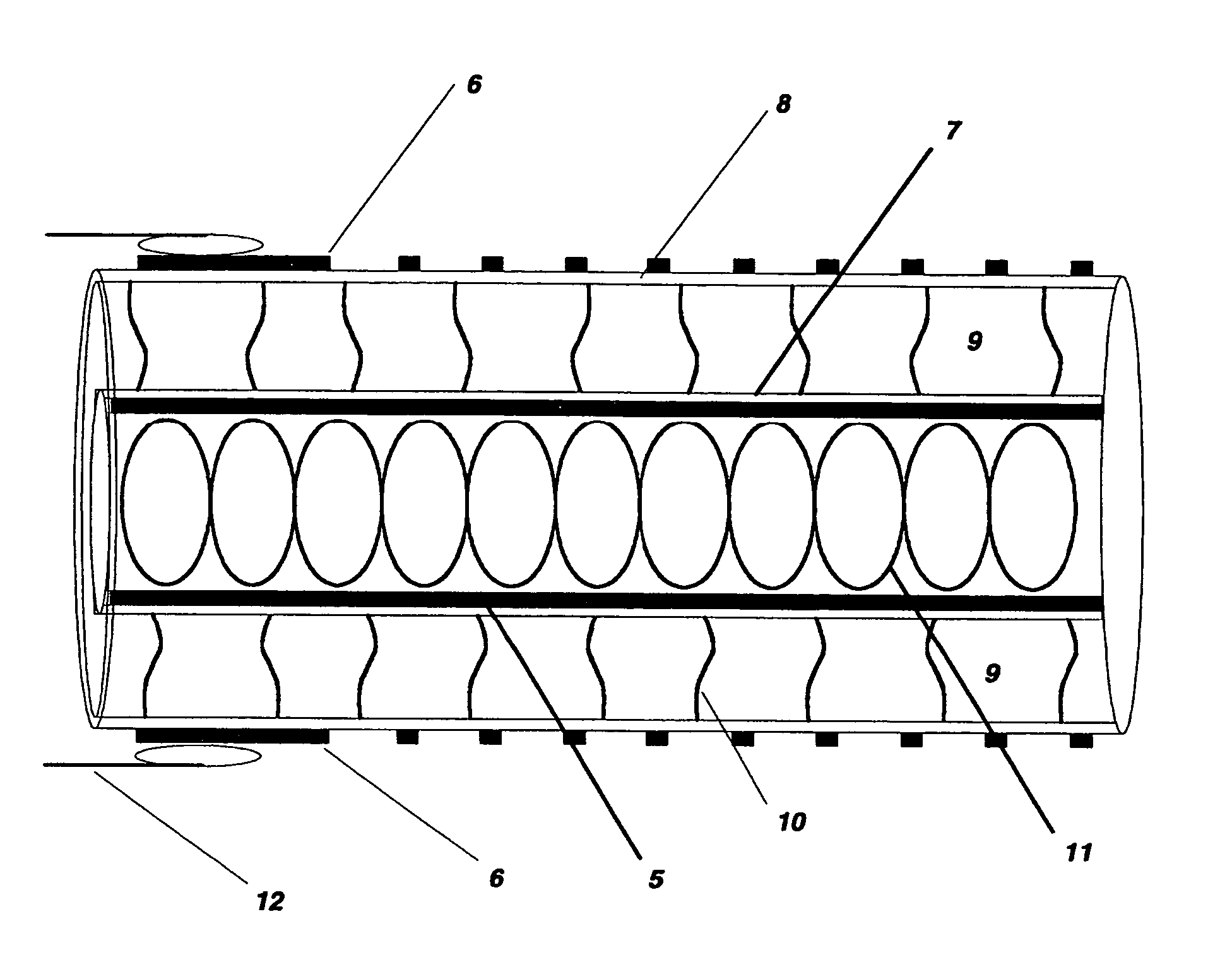
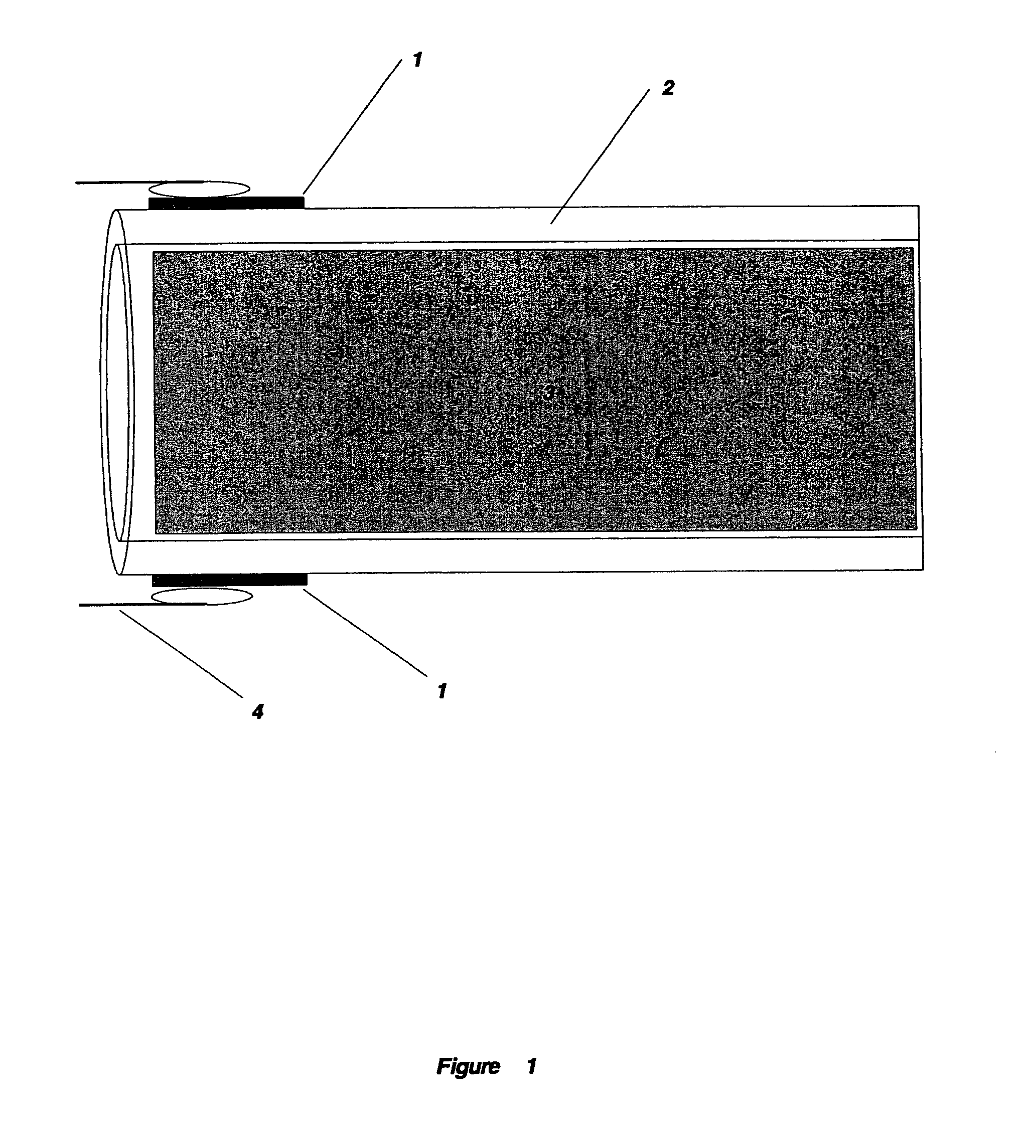
[0030] Turning now to the drawings, FIG. 1 shows one embodiment of the electrodes 1 attached to a glass tube, or envelope 2. As shown in this embodiment, the electrode 1 concentrically surrounds the glass tube 2 (although, as in the second embodiment described above one of the electrodes would be on the inside of a glass tube). The electrodes 1 are placed on the outside of the glass tube 2 such that they are physically separated from the heated plasma 3 and associated energetic ions or electrons. The attachment of the electrodes 1 to the glass tube 2 substantially eliminates gaps and pores in the contact. The electrical contact 4 to the electrodes 1 can be mechanical through compressive spring contact but numerous techniques such as, but not limited to, soldering and welding are possible. The thicknesses implied by the scale in FIG. 1 of the electrode 1 and glass tube 2 are for representation only and are not indicative of the actual or relative thicknesses.

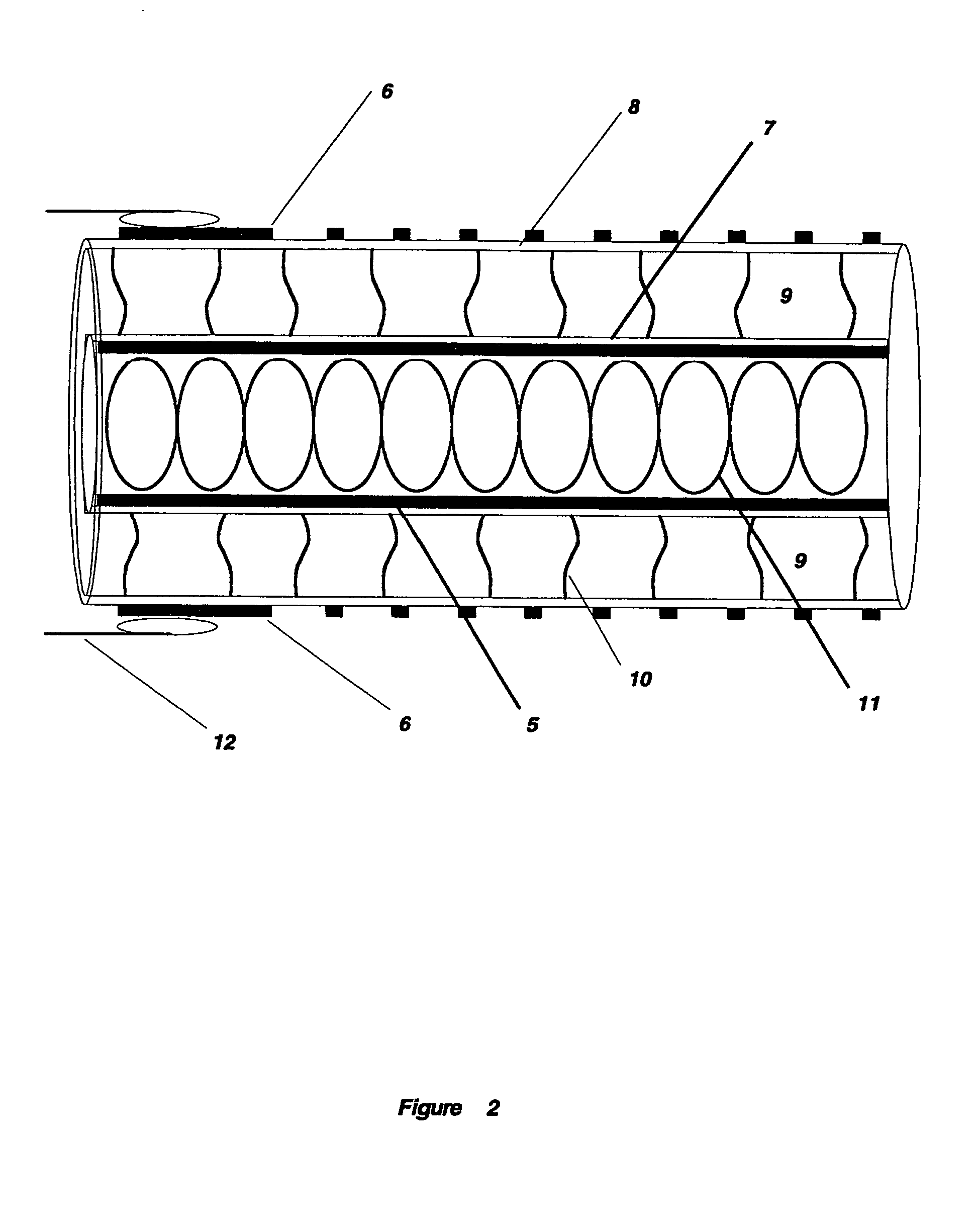
[0031]FIG. 2 shows one em...


PUM


Abstract

An efficient, intense ultraviolet radiation source is disclosed that uses electrodes, external to the UV-generating plasma, to eliminate electrode erosion. High-frequency electrical energy is coupled to the UV-emitting plasma capacitively. The electrodes are attached to the glass envelope in such a way as to minimize or eliminate resistive or capacitive losses. The intense ultraviolet radiation source can be generated by applying a continuous or pulsed / gated high-frequency voltage to the glass envelope via the external electrodes. Electrode erosion is eliminated as a reason for lamp failure and the peak intensity that can be generated without damage is greatly increased.

Description

FIELD OF THE INVENTION [0001] This invention relates generally to the field of ultraviolet radiation sources, and more particularly to efficient ultraviolet radiation sources generating wavelengths less than 254 nm. The improved efficiency allows economical use of ultraviolet sources for a wide range of applications. A method and apparatus for such ultraviolet radiation sources is disclosed. BACKGROUND OF THE INVENTION [0002] Ultraviolet radiation (UV) is the electromagnetic radiation having wavelengths between that of x rays and visible light, with wavelengths of about 100 nanometers (nm) to about 400 nm. Ultraviolet radiation can be further divided into spectral bands: UV-A, having wavelengths in the range of about 320 nm to about 400 nm, UV-B, having wavelengths of about 290 nm to about 320 nm, and UV-C, having wavelengths between about 290 nm and about 180 nm. The shorter the wavelength of the ultraviolet radiation, the higher the photon energy, and the more useful the radiation...

Claims


Application Information

Patent Timeline
IPC IPC(8): C02FH01J17/00H01J17/20H01J61/00H01J65/04
CPCH01J65/046
Inventor SPIELMAN, RICK B.FRAIM, MICHAEL L.MERVINI, JOSEPH A.
Owner ABQ ULTRAVIOLET POLLUTION SOLUTIONS
Learn More