Electrochemical cell and fabrication method of the same

Inactive Publication Date: 2005-02-17
SEIKO INSTR INC +1
View PDF3 Cites 26 Cited by
  • Summary
  • Abstract
  • Description
  • Claims
  • Application Information

AI Technical Summary

Benefits of technology

[0071] As described above, the invention exerts the advantages that enhance the flexibility of the shapes of the electrochemical cell to facilitate the reduction in size and

Problems solved by technology

However, since the packages of ICs, and quartz and SAW devices placed on the mounting substrate are formed in a rectangular shape, space is created when the electrochemical cell is arranged.
Thus, dead space is created to increase the occupied area when the cell is arranged on the mounting substrate, and it is

Method used


Image

  • Electrochemical cell and fabrication method of the same
  • Electrochemical cell and fabrication method of the same
  • Electrochemical cell and fabrication method of the same

Examples


example 1

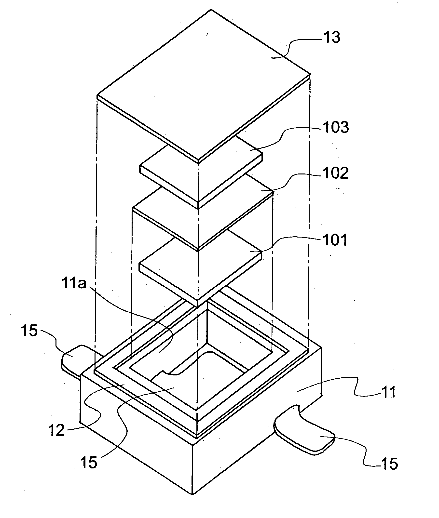
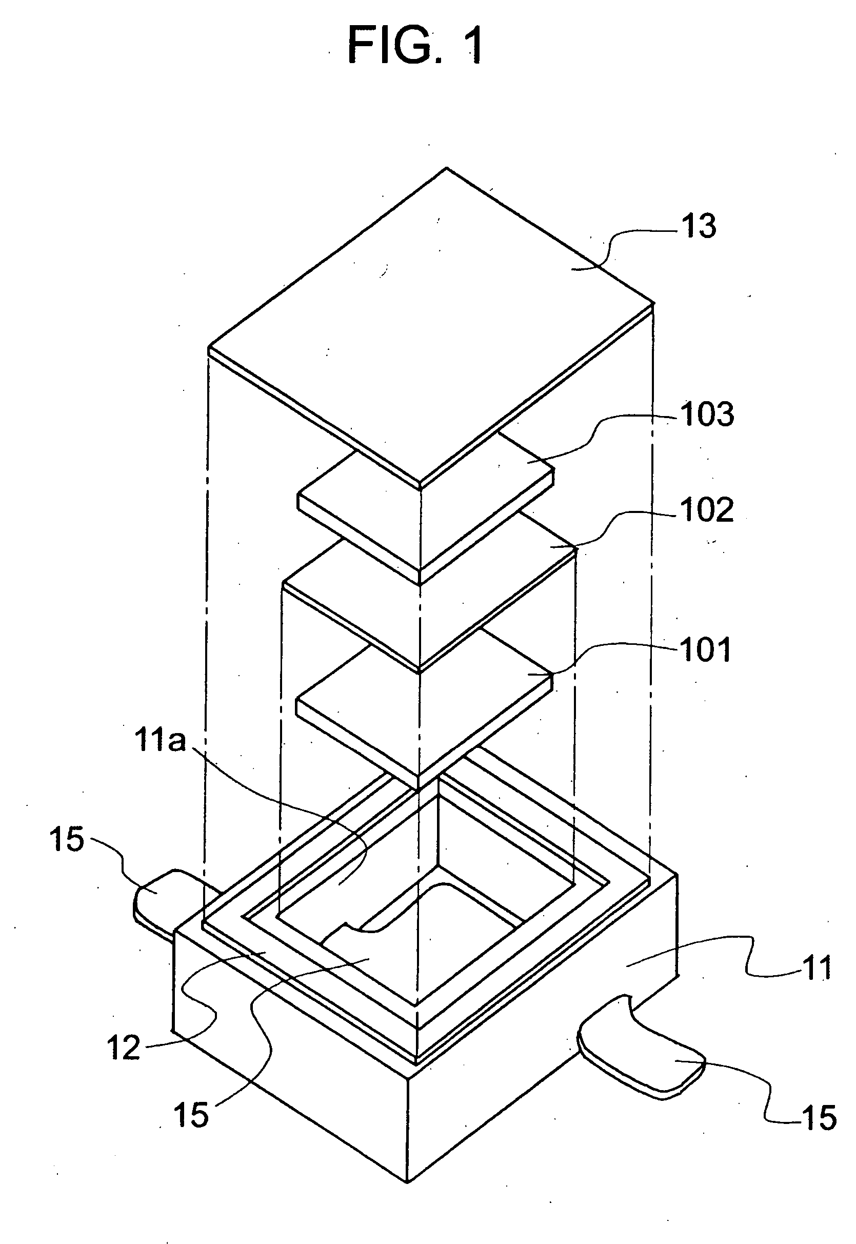
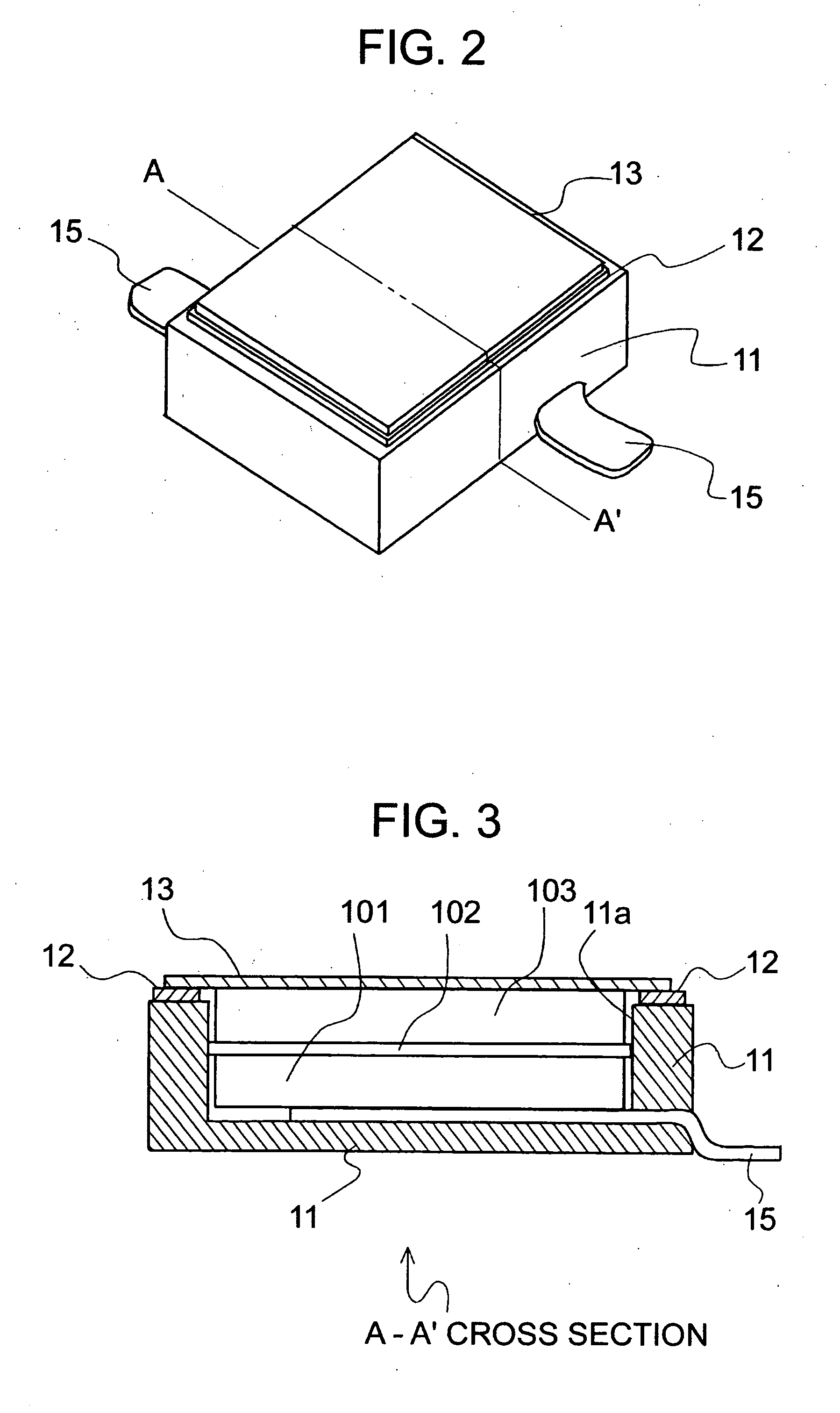
[0095]FIG. 1 shows a schematic diagram illustrating an electrochemical cell according to the invention. FIG. 2 shows an outside diagram illustrating the electrochemical cell according to the invention. FIG. 3 shows a cross-sectional view illustrating the electrochemical cell according to the invention.

[0096] In this example, an epoxy was used for a base member 11, and 18 Cr-12 Ni—Mo—Cu steel of stainless steel was used for a conductive terminal 15. Tin was plated over the portions where the conductive terminal 15 was extended to the outer wall of the base member 11 for facilitating solder joint to a mounting substrate. 42 Ni-Fe alloy was used for a frame member 12 and a cover member 13. An active material was prepared by kneading carbon black as a conductive material and PTFE as a binder with activated carbon commercially available. The kneaded product was rolled by roll press to form into a sheet, and it was cut to form a positive electrode active material 101 and a negative elect...

example 2

[0098]FIG. 4 shows an outside diagram illustrating an electrochemical cell according to the invention. FIG. 5 shows a cross-sectional view illustrating the electrochemical cell according to the invention.

[0099] In a cover terminal, one end thereof is connected to the side surface of a cover member and extended therefrom. It is bent in parallel with the side surface of the base member, and extended along the side surface of the base member to the bottom part. The other end thereof is bent on a surface contacting with a land, and has the surface contacting with the land on almost the same plane as the bottom surface of the base member. One end of a conductive terminal is placed on the bottom surface inside a container, and the other end thereof is extended through outside the container. This other end is also bent on a surface contacting with the land, and has the surface contacting with the land on almost the same plane as the bottom surface of the base member.

[0100] An epoxy was u...

example 3

[0102] For a base member 11, the base member 11 was formed of polyphenylene sulfide of a thermoplastic resin.

[0103] Aluminium was used for a conductive terminal 15. Nickel was plated over a portion where the conductive terminal 15 was extended from the outer wall of the base member 11, for facilitating solder joint to a mounting substrate. 42 Ni—Fe alloy was used for a frame member 12 and a cover member 13. An active material was prepared by kneading carbon black as a conductive material and PTFE as a binder with activated carbon commercially available. The kneaded product was rolled by roll press to form into a sheet, and it was cut to form a positive electrode active material 101 and a negative electrode active material 103. For an electrolyte, (C2H5)4NBF4 was dissolved in PC for use. The cover member 33 was plated with nickel 2 μm in thickness and gold 0.5 μm in thickness, and the frame member 12 was plated with nickel 2 μm in thickness for seam welding of the resistance heating...


PUM

PropertyMeasurementUnit
Temperatureaaaaaaaaaa
Fractionaaaaaaaaaa
Thicknessaaaaaaaaaa

Abstract

An electrochemical cell is provided which facilitates the reduction in size and thickness. An electrochemical cell is configured of a base member made of a resin material and formed in a box shape, a conductive terminal made of a metallic material and fixed and penetrated from the inside to the outside of the base member, a frame member made of a metallic material and fixed to the base member, and a cover member welded with the frame member.

Description

BACKGROUND OF THE INVENTION [0001] 1. Field of the Invention [0002] The present invention relates to an electrochemical cell such as a non-aqueous electrolyte cell and an electric double layer capacitor utilizing electric double layer theory, and to a fabrication method of the same. [0003] 2. Description of the Related Art [0004] The electrochemical cell such as the non-aqueous electrolyte cell and the electric double layer capacitor is used for a backup power source of clock functions, a backup power source of semiconductor memories, an auxiliary power source of electronic devices such as a microcomputer and an IC memory, a battery of solar-powered clocks, and a power source for driving motors. With the realization of non-volatile semiconductor memories and reduced power consumption of clock function devices, the electrochemical cell is not required for large capacity and large current so much. Instead, for the needs of the electrochemical cell, an increasing demand is that compone...

Claims


Application Information

Patent Timeline
IPC IPC(8): H01G2/02H01G2/24H01G9/12H01G9/00H01G11/00H01G11/14H01G11/22H01G11/38H01G11/42H01G11/66H01G11/74H01G11/78H01G11/82H01G11/84H01G11/86H01J29/80H01L23/057H01L23/10H01L23/498H01M2/02H01M2/04H01M2/06H01M2/12H01M2/30H01M10/05H01M10/0585H05K5/00H05K5/04H05K5/06
CPCH01L23/057Y10T29/49108H01L23/49861H01L24/48H01L2224/48091H01L2224/48247H01L2924/01078H01L2924/01079H01L2924/15153H01L2924/15165H01L2924/16195H01L2924/19041H01L23/10H01L2924/00014H01L2924/12042H01L2224/05599H01L2224/85444H01L2224/85455H01L2224/8547H01L2224/45099H01L2924/14Y02P70/50H01L2924/00H01L2224/45015H01L2924/207
Inventor ITOH, HIRONOBUMAKISHIMA, YUTAKAONODERA, HIDEHARUYUZURIHARA, KAZUTAKA
Owner SEIKO INSTR INC
Why Eureka
Try Eureka