
X-ray apparatus with field emission current stabilization and method of providing x-ray radiation therapy

a field emission current and x-ray radiation technology, applied in the field of x-ray radiation, can solve the problems of affecting inability to accurately calculate the actual dose of radiation therapy,

Inactive Publication Date: 2005-02-17
MINNESOTA MEDICAL PHYSICS LLC
View PDF8 Cites 4 Cited by
  • Summary
  • Abstract
  • Description
  • Claims
  • Application Information

AI Technical Summary

Benefits of technology

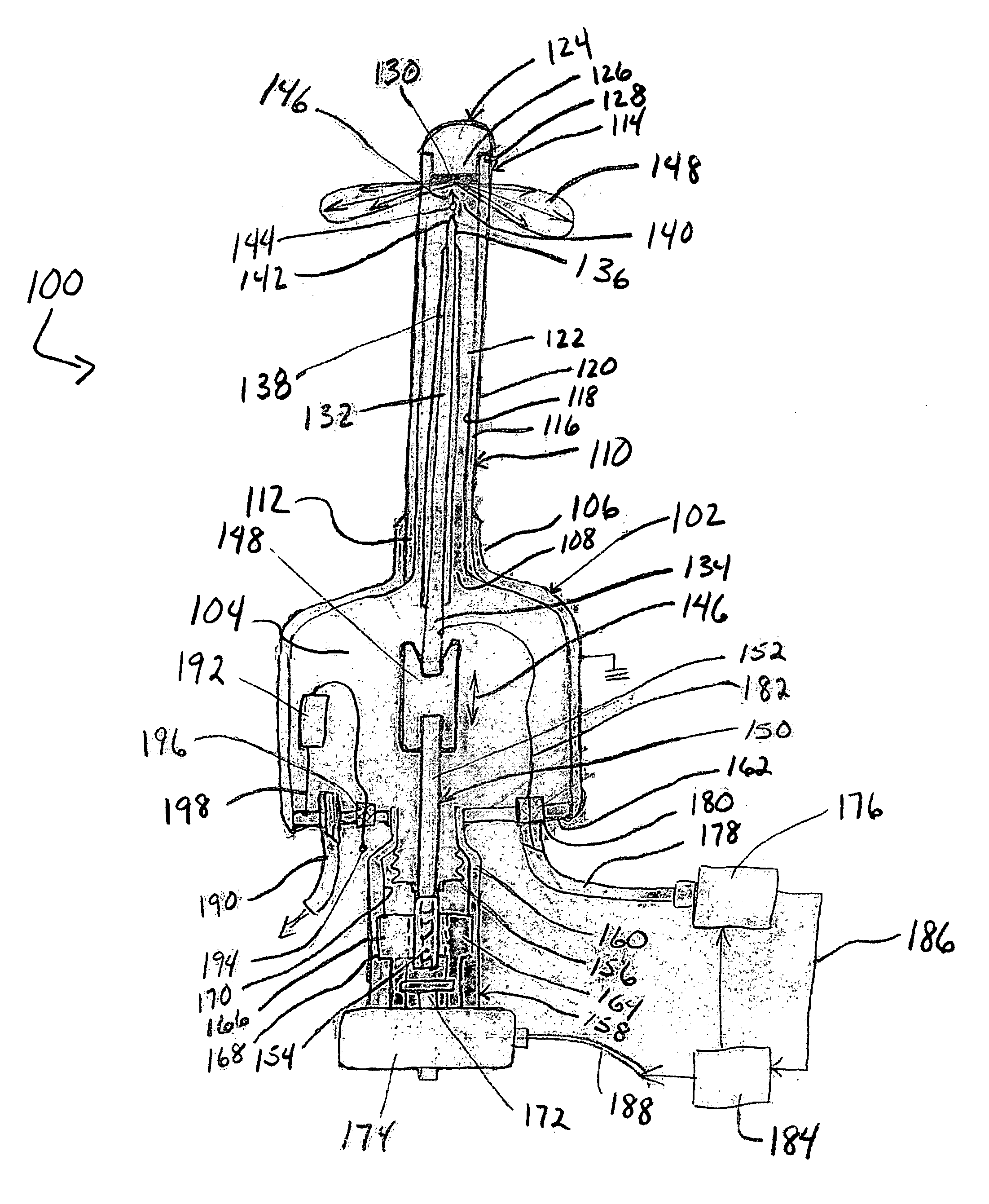
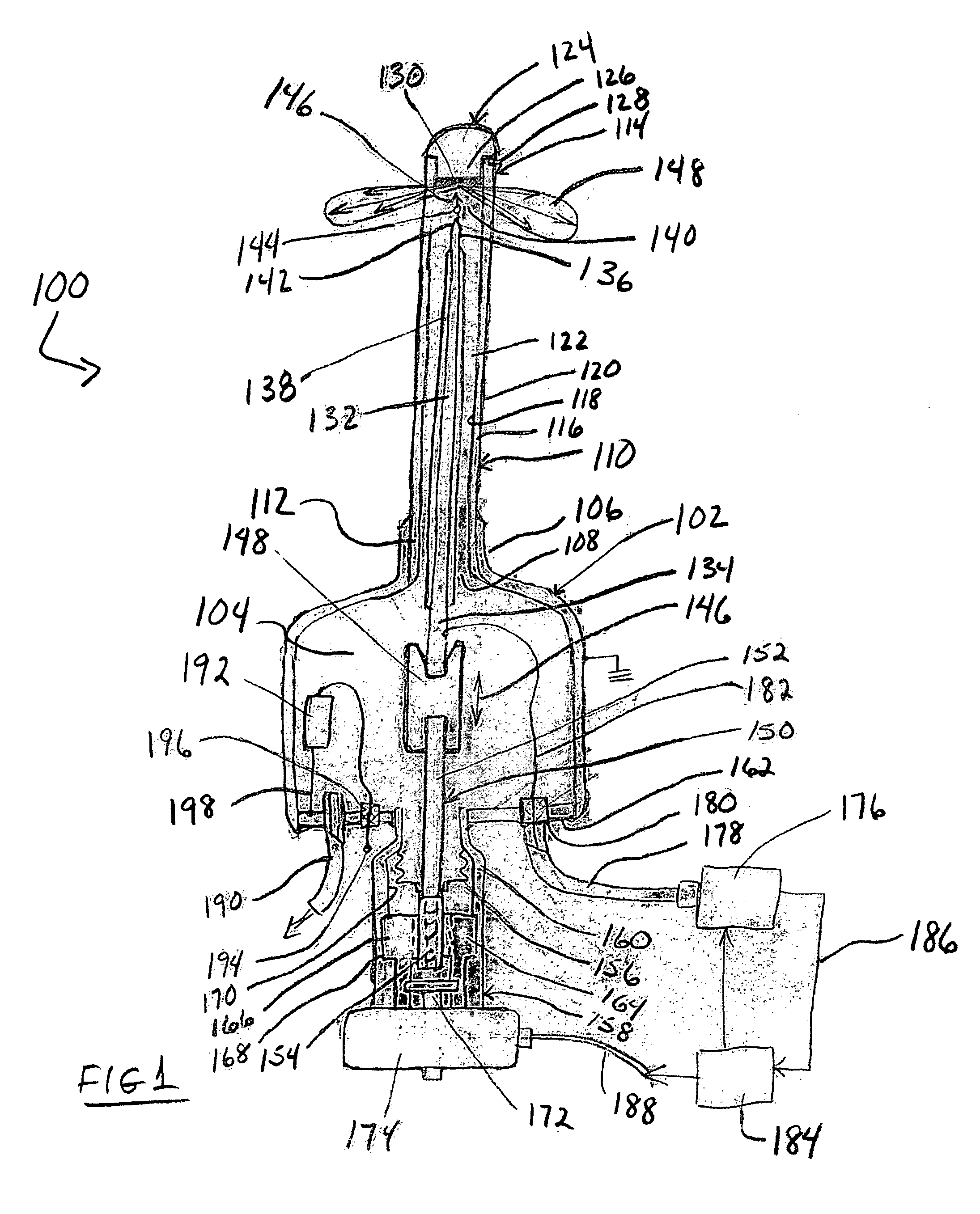
[0012] The present invention provides an apparatus and method for radiation therapy that enables the operator to exercise independent control of the voltage and operating current, thus providing the operator with the ability to stabilize the applied radiation dose supplied to the target site. An apparatus in accord with the present invention will have a field emission cathode that produces an electron beam in response to an applied operating voltage and an anode having a target material that generates x-rays when struck by the electron beam. The cathode and anode are separated by a gap changeable in size in response to the x-ray output of the device to maintain the dose at the desired level.
[0013] A method in accord with the present invention will involve steps of identifying a target site for radiation therapy; disposing a field emission x-ray apparatus having a cathode and an anode separated by a gap in proximity to the target site; monitoring the operating current of the x-ray apparatus; and adjusting the gap to maintain the desired operating current. Adjusting the gap enables the operator to control the operating current, thereby enabling compensation for possible instabilities in the field emission of electrons, including but not limited to instabilities caused by the state of the cathode emission surface, drift of operating parameters with time, and temperature.

Problems solved by technology

Where the target site was internal, such as a tumor, the applied x-ray radiation had to traverse the skin and other soft tissue and perhaps bone on its way to the target site, resulting in damage and burn to those tissues.
Among other reasons, this disadvantage of x-ray therapy using external x-ray sources caused innovators to seek devices and methods to generate x-rays internally.
First, the x-ray system has an inherent instability of its electron beam in the presence of a magnetic field.
Because the thermionically generated electron beam must traverse the length of the probe between the electron gun and the target assembly, stray external magnetic fields can cause the beam to be deflected away from the target causing the generated x-ray flux to vary and complicating the calculation of the dose actually received by the patient.
Another drawback is that the apparatus includes an electron gun, which significantly adds both complexity and cost.
Still another deficiency in this system is that the inflated balloon does not fix the position of the x-ray source relative to the patient's body and thus it requires an additional system for ensuring that the x-ray emitter is in the right position against the tissue to be irradiated.
The drawbacks of the disclosed X-ray source are its relative complexity, large size and lack of adequate means for delivery of an optimal distribution of radiation dose across the predetermined volume of the target tissue.
It is not adapted for and cannot be used for treatment of tumors inside the body.
Another drawback of the x-ray tube is an absence of the ability to control the operating current and voltage independently.
This particular disadvantage inhibits manufacturing reproducibility.
An undesirable feature of known field x-ray emitter devices is the inability to closely control the dose rate.
Because of the inconsistency in the current and thus the x-ray beam flux, the dose applied during any particular therapy session may not be well known, which leads to inconsistent treatment and results.

Method used


Image

  • X-ray apparatus with field emission current stabilization and method of providing x-ray radiation therapy
  • X-ray apparatus with field emission current stabilization and method of providing x-ray radiation therapy
  • X-ray apparatus with field emission current stabilization and method of providing x-ray radiation therapy

Examples


Embodiment Construction

[0035] An embodiment of an x-ray apparatus with gap size control 100 is shown in FIG. 1. Apparatus 100 includes a housing 102 that defines a vacuum chamber 104. Housing 102 can take substantially any desired form and as shown has a substantially cylindrical configuration. Housing 102 may include a collar 106 that may, if desired and as shown, be integral with the housing 102. Collar 106 forms an opening 108 into the housing 102 that is configured to receive a probe 110 having proximal and distal ends 112 and 114, respectively. Collar 106 receives proximal end 112 in a sealing engagement to preserve the vacuum within housing 102. While a protruding collar 106 is illustrated in the Figure, other known forms of sealing engagements and configurations therefor can be used with equal facility in the present invention so long as a vacuum can be maintained.

[0036] Probe 110 may have an elongate, tubular or needle-like configuration as shown in the Figure. It will be understood that while th...


PUM


Abstract

The present invention provides apparatus and method for providing a stabilized x-ray output from a field emission x-ray apparatus by monitoring the operating current and adjusting the gap between the anode and cathode to stabilize the output.

Description

[0001] The present application claims priority from U.S. patent application Ser. No. 10 / 392,167, entitled “X-Ray Apparatus With Field Emission Current Stabilization And Method Of Providing X-Ray Radiation Therapy” and filed on Mar. 19, 2003. [0002] The present invention relates generally to apparatus and method for providing x-ray radiation therapy and specifically to apparatus and method for providing x-ray radiation therapy with real-time stabilization of the operating current, and thus the dosage rate.BACKGROUND OF THE INVENTION [0003] The use of x-ray radiation for medical and non-medical applications is well known. In the medical arena, x-ray radiation therapy is a commonly used and accepted practice in the treatment of disease, including but not limited to, for example, tumors, certain skin diseases, and / or benign conditions. Historically, treatment first utilized external x-ray sources that supplied x-ray radiation to the target site. Where the target site was internal, such ...

Claims


Application Information

Patent Timeline
IPC IPC(8): A61N5/10H01J35/06H01J35/32
CPCA61B1/32A61N5/1001A61N5/1014H01J2235/164H01J35/32H01J2235/064H01J35/065
Inventor JAAFAR, ALICHORNENKY, VICTOR I.
Owner MINNESOTA MEDICAL PHYSICS LLC
Learn More