
Control of plasma transitions in sputter processing systems

Active Publication Date: 2005-02-24
MKS INSTR INC
View PDF36 Cites 223 Cited by
  • Summary
  • Abstract
  • Description
  • Claims
  • Application Information

AI Technical Summary

Benefits of technology

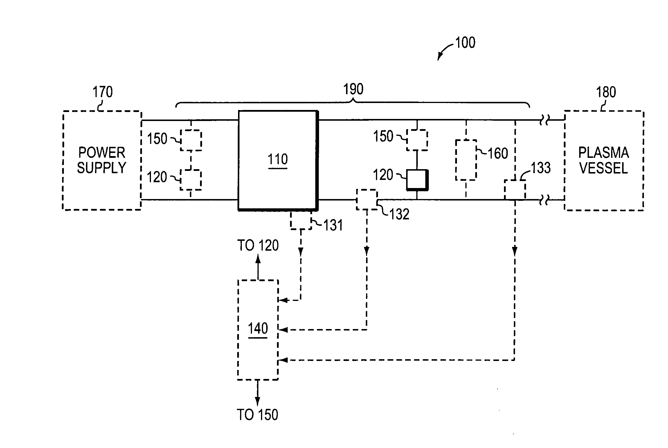
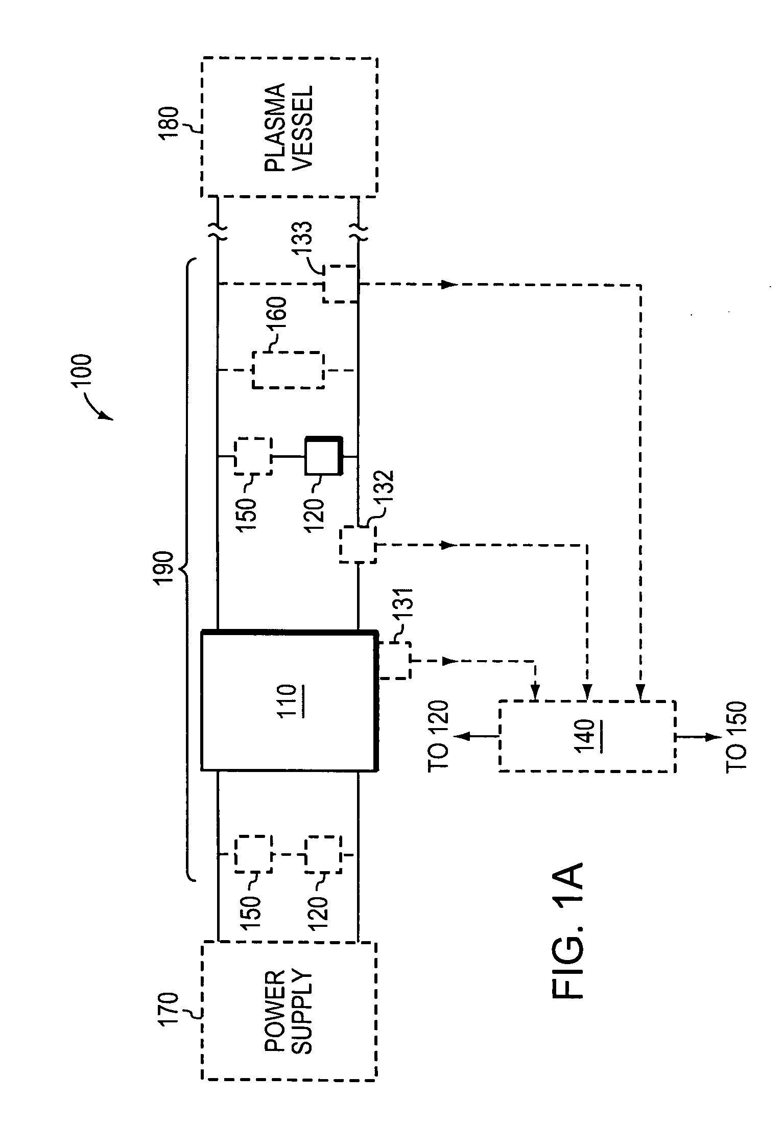
[0008] The invention, in part, arises from the realization that the cooperative action of a resonant circuit and a shunt switch can provide improved response to arc initiation, improved transition between different plasma states, and improved ignition of a plasma. According to principles of the invention, a resonant circuit, when shunted, can drive a plasma current to zero and thus extinguish the plasma in a brief period of time that effectively reduces, for example, arc related damage. Cooperative action of the resonant circuit and the shunt can also improve ignition of glow and arc discharge plasmas.
[0011] The sensor can be configured to sense a flux induced by an inductor of the resonant circuit. The sensor can be a coil placed adjacent to the inductor. Such a sensor can provide quick detection of the onset of an arc plasma during glow plasma processing. The switch unit can have a resistance that is large enough to effectively act as a damping impedance for the resonant circuit during shunting.
[0014] The apparatus can further include a voltage sensor for sensing a voltage of at least one of the resonant circuit, the power supply, and the input of the plasma vessel. The apparatus can further include a current sensor for sensing a current of at least one of the resonant circuit, the power supply, and the input of the plasma vessel. The additional sensors can provide improved detection of plasma state transitions.
[0016] In response to detection of a state change, for example, the transition from a glow plasma mode to an arc plasma mode, shunting can include substantially reducing a current flowing through the plasma vessel during an initial half cycle of the resonant circuit relative to a current flowing through the vessel prior to the initial half cycle. The shunt can be removed for the next half cycle before again shunting if the arc discharge plasma persists. The shunt and wait cycle can be repeated until the original plasma mode is restored, in response to feedback from one or more sensors.

Problems solved by technology

Undesired arcing is a significant problem for the performance of sputter PVD systems.
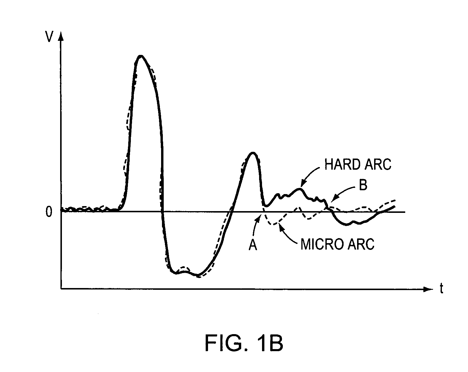
Inherently, plasma noise produces a certain amount of “micro-arcing” within a glow plasma inside the deposition chamber.
However, the micro-arcing may develop into more severe plasma arcing, or “hard arcing”, within the chamber.
An arc can remove the poisoning from the target, but it may also generate undesirable particles.
Some power supplies may exacerbate the problems associated with plasma arcing.
Moreover, periodic suppression circuitry adds significant cost.

Method used


Image

  • Control of plasma transitions in sputter processing systems
  • Control of plasma transitions in sputter processing systems
  • Control of plasma transitions in sputter processing systems

Examples


Embodiment Construction

[0035] A “plasma system” is an apparatus that includes plasma generation components, and can include materials processing components. A plasma system can include one or more vessels, power supply components, metrology components, control components, and other components. Processing can occur in the one or more vessels and / or in one or more processing chambers in communication with the one or more vessels. A plasma system can be a source of plasma or reactive gas species generated in a plasma or can be a complete processing tool.

[0036] A “vessel” is a container or portion of a container that contains a gas and / or a plasma, and within which a plasma can be ignited and or / maintained. A vessel is combined with other components, such as power generation and cooling components to form a plasma processing system.

[0037] A “plasma” is a state of matter that includes a collection of energetic charged particles that can be developed through application of a combination of electrcal and magne...


PUM

PropertyMeasurementUnit
Timeaaaaaaaaaa
Electrical resistanceaaaaaaaaaa

Abstract

Methods and apparatus for controlling a plasma used for materials processing feature cooperative action of a resonant circuit and a switch unit coupled to a plasma vessel and a power supply. A sensor for acquiring a signal associated with a state of a plasma in the plasma vessel supports closed-loop control of the switch unit. Undesirable plasma states detected by the sensor can be eliminated by closing the switch unit to shunt the resonant circuit.

Description

FIELD OF THE INVENTION [0001] The present invention relates generally to plasma-based materials processing. More particularly, the invention relates to control of arcs and control of plasma state transitions in plasma processing systems. BACKGROUND OF THE INVENTION [0002] Many manufacturing operations utilize plasma processing. Plasma-enhanced Vapor Deposition (PVD), for example, is increasingly used for deposition of thin metallic and non-metallic films. Most PVD systems are either of the cathodic arc or sputtering types. While the arc discharge plasma utilized in a cathodic arc PVD systems is characterized by high currents and low voltages, the glow plasma utilized in sputter PVD systems is characterized by lower currents and higher voltages. Sputter PVD systems often include features that provide magnetic fields to support electric field ionization of the glow plasma. [0003] A glow plasma and an arc discharge plasma, under appropriate conditions, can exhibit mode shifts. For exam...

Claims


Application Information

Patent Timeline
IPC IPC(8): B23K10/00H01J37/32
CPCB23K10/00H01J2237/0206H01J37/32935H01J37/32082H01J37/34H01J37/32
Inventor SELLERS, JEFF C.
Owner MKS INSTR INC
Learn More