Molecular beam epitaxy growth apparatus and method of controlling same

a growth apparatus and beam epitaxy technology, applied in the growth process of polycrystalline materials, crystal growth processes, chemically reactive gases, etc., can solve the problem of difficult control of the ratio between as and p within the crystal

Inactive Publication Date: 2005-03-03
SHARP KK
View PDF4 Cites 9 Cited by
  • Summary
  • Abstract
  • Description
  • Claims
  • Application Information

AI Technical Summary

Benefits of technology

[0025] In embodiment(s) of the present invention where molecular beam(s) is/are being pulsed for intermittency control, it is preferred in order to obtain uniform crystal(s) that at least two atomic layers be grown per cycle. Accordingly, where deposition rate is 0.5 μ/hour, carrying out control such that period(s) is/are not ...

Problems solved by technology

When growing crystals for formation of active layers in laser elements, control of the alloy ratios of the respective elements within the crystal is an important issue for causing the laser to emit at constant wavelength.
However,...

Method used


Image

  • Molecular beam epitaxy growth apparatus and method of controlling same
  • Molecular beam epitaxy growth apparatus and method of controlling same
  • Molecular beam epitaxy growth apparatus and method of controlling same

Examples


embodiment 1

Overview of Molecular Beam Epitaxy Growth Apparatus

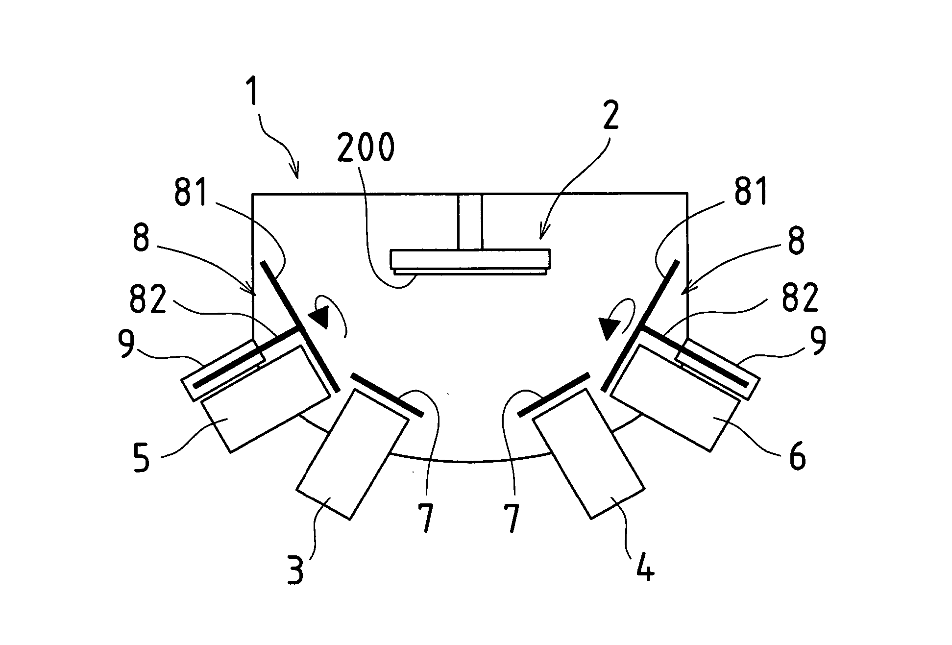
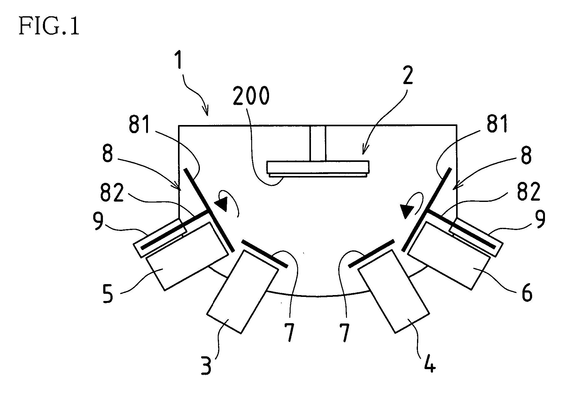
[0037]FIG. 1 is a drawing showing in schematic fashion an example of a molecular beam epitaxy growth apparatus in accordance with the embodiment 1.

[0038] The molecular beam epitaxy growth apparatus of the present example is equipped with vacuum chamber 1, substrate manipulator 2, Ga cell (Group III molecular beam source cell) 3, In cell (Group III molecular beam source cell) 4, As cell (Group V molecular beam source cell) 5, P cell (Group V molecular beam source cell) 6, and so forth.

[0039] Vacuum chamber 1 is evacuated to 2×10⁻⁹ Pa with all heater(s) (not shown) turned OFF. Substrate manipulator 2 is installed in the upper central region of vacuum chamber 1.

[0040] Substrate manipulator 2 has built thereinto substrate heating mechanism(s) and substrate rotating mechanism(s) (neither of which is shown), permitting substrate 200, which is held by this substrate manipulator 2, to be maintained at constant temperature and to be rota...

embodiment 2

[0069]FIGS. 7 and 8 are respectively a front view and a plan view showing in schematic fashion a different exemplary constitution for a molecular beam epitaxy growth apparatus in accordance with the embodiment 2.

[0070] The molecular beam epitaxy growth apparatus of the present example is equipped with vacuum chamber 1, substrate manipulator 2, Ga cell (Group II molecular beam source cell) 3, In cell (Group III molecular beam source cell) 4, As cell (Group V molecular beam source cell) 5, P cell (Group V molecular beam source cell) 6, and so forth.

[0071] Vacuum chamber 1 is evacuated to 2×10⁻⁹ Pa with all heater(s) (not shown) turned OFF. Substrate manipulator 2 is installed in the upper central region of vacuum chamber 1.

[0072] Substrate manipulator 2 has built thereinto substrate heating mechanism(s) and substrate rotating mechanism(s) (neither of which is shown), permitting substrate 200, which is held by this substrate manipulator 2, to be maintained at constant temperature an...


PUM


Abstract

In system(s) utilizing multiple molecular beams of Group V material(s) (and/or Group VI material(s)), rotary beam chopper(s)) 8 and so forth are installed in front of respective discharge port(s) of such plurality of Group V molecular beam source cell(s) 5, 6 (and/or Group VI molecular beam source cell(s)); intermittency control causing molecular beam(s)) discharged from respective molecular beam source cell(s) 5, 6 to be repeatedly blocked and discharged in periodic fashion is carried out; and mutual synchronization of such molecular beam(s)) subjected to intermittency control causes supply of respective molecular beam(s)) of multiple Group V materials (and/or Group VI materials) in sufficient quantity or quantities as necessary for crystal growth, with alloy ratio(s) within crystal(s) being efficiently controlled.

Description

CLAIM(S) IN CONNECTION WITH RELATED APPLICATION(S) AND / OR PRIORITY RIGHT(S) [0001] This application claims priority under 35 USC 119(a) to Patent Application No. 2003-300078 filed in Japan on 25 Aug. 2003, the content of which is incorporated herein by reference in its entirety.BACKGROUND OF THE INVENTION [0002] The present invention relates to molecular beam epitaxy (MBE) growth apparatus and method of controlling same. [0003] Structure of a typical molecular beam epitaxy growth apparatus (MBE apparatus) is shown in FIG. 9. [0004] The molecular beam epitaxy growth apparatus shown in FIG. 9 is equipped with vacuum chamber 101 which can be evacuated to ultrahigh vacuum; substrate manipulator 102 which heats and rotates substrate 200 as substrate 200 is held at a prescribed location within this vacuum chamber 101; a plurality of molecular beam source cells 103, 104, 105, 106 radiating molecular beams toward the surface of substrate 200; and cell shutters 107 respectively installed at ...

Claims


Application Information

Patent Timeline
IPC IPC(8): C30B23/08C30B23/02C30B29/42C30B35/00H01L21/203
CPCC30B35/00C30B29/42C30B23/02C30B23/002
Inventor KAWASAKI, TAKASHI
Owner SHARP KK
Why Eureka
Try Eureka