Method of producing thin film or powder array using liquid source misted chemical deposition process

a technology of chemical deposition process and thin film, which is applied in the direction of liquid/solution decomposition chemical coating, cell components, physical/chemical process catalysts, etc., can solve the problems of difficult synthesis of a material having a uniform phase, high cost and low effectiveness of research for developing new materials, and no general rule that can be predicted. , to achieve the effect of achieving uniform phase, the effect of improving the efficiency of the uniform phas

Inactive Publication Date: 2005-03-03
KOREA ADVANCED INST OF SCI & TECH
View PDF5 Cites 12 Cited by
  • Summary
  • Abstract
  • Description
  • Claims
  • Application Information

AI Technical Summary

Benefits of technology

[0012] The inventors attempted to solve the aforementioned prior art problems and devised a method of this invention. Accordingly it is an object of the invention to provide a method of producing a metal, metal oxide thin-film or powder array having a uniform phase more efficiently than by the prior art method, in that two or more types of

Problems solved by technology

Although chemical experiment has been widely carried out for synthesizing many materials, however, no general rule has been found that can be predicted by a composition and structure of a material and a reaction path of solid compounds.
This results in continued research of high cost and low effectiveness for developing new materials of the multicomponent system where synthesis and analysis of a new compound is based on existing knowledge and principles.
Since it is intended to obtain a uniform phase through diffusion between solid layers, the reaction itself between solids is very difficult and thermal treatment conditions are very tightened, resulting in difficult synthesis of a material having a uniform p

Method used


Image

  • Method of producing thin film or powder array using liquid source misted chemical deposition process
  • Method of producing thin film or powder array using liquid source misted chemical deposition process
  • Method of producing thin film or powder array using liquid source misted chemical deposition process

Examples


embodiment 1

[0035] Producing a Ferroelectric Thin Film Array

[0036] Embodiment 1-1: Producing a thin film array of (Bi,La,Ce)4Ti3O12 (BLCT) (I)

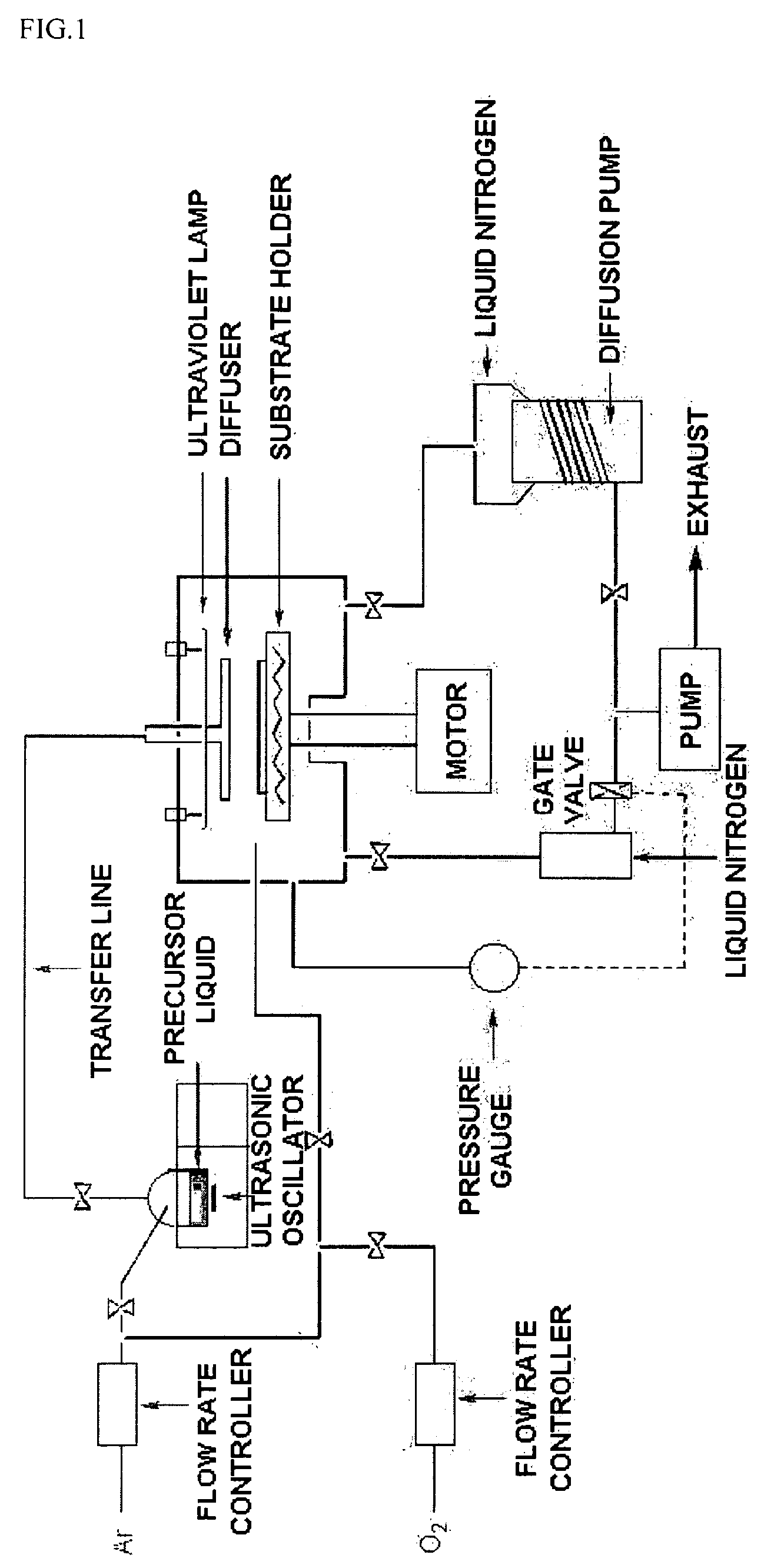
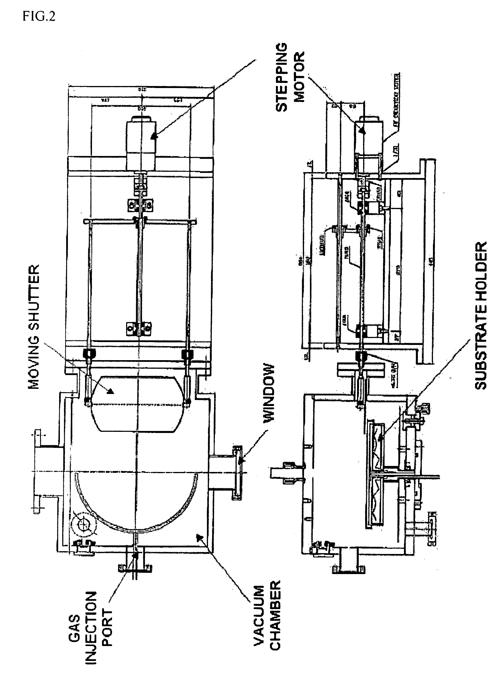
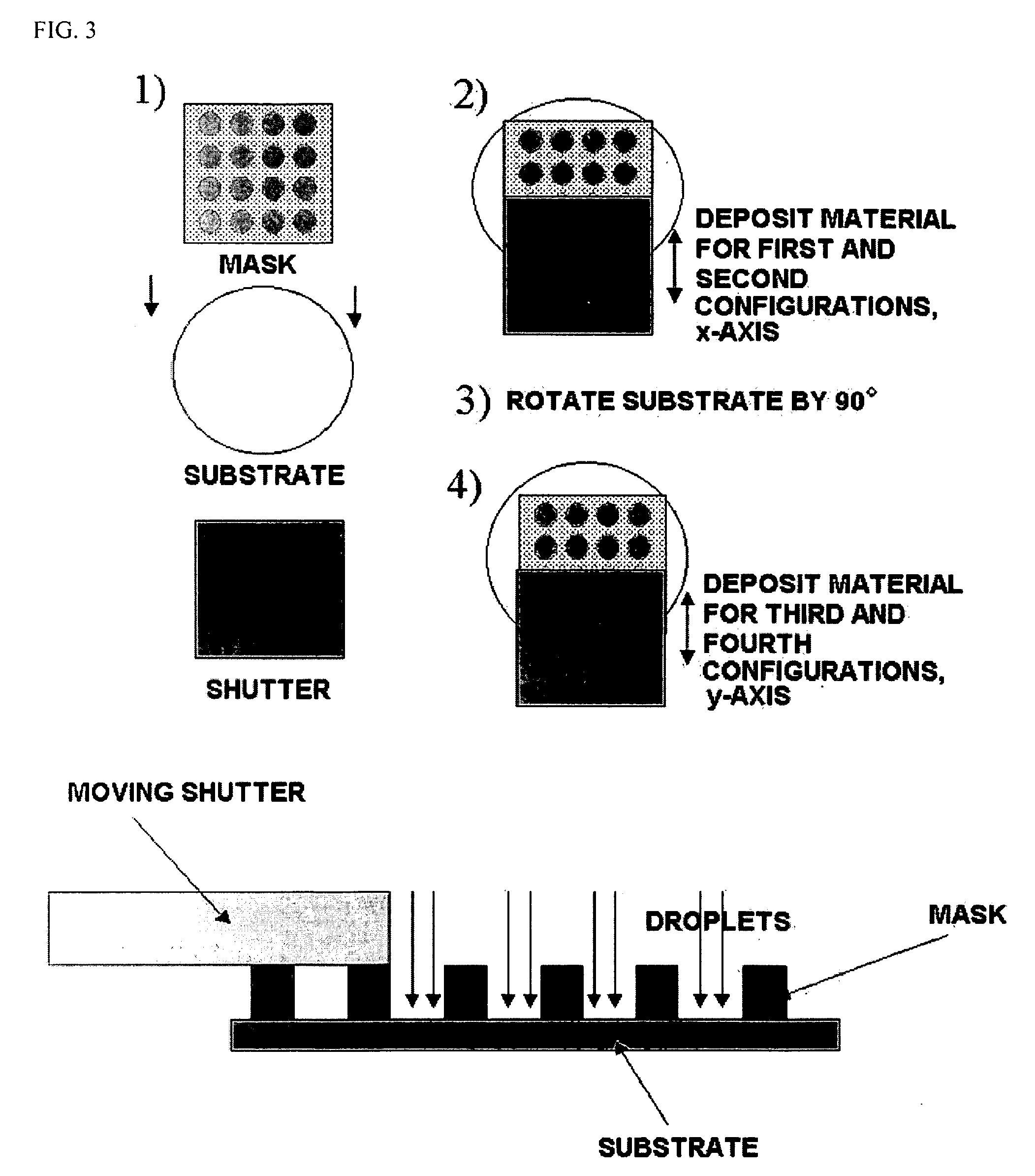
[0037] Bismuth nitrate {Bi(NO3)3.6H2O} that is a precursor of bismuth, lanthanum nitrate {La(NO3)3.6H2O} and titanium isoproxide {Ti(O—iC3H7)} that are precursors of lanthanum and titanium are used. These precursors are dissolved in 2-methoxyethanol (CH3OCH2CH2OH) in conformity to the stoichiometric ratio (Bi:La:Ti=3.25:0.75:3) to produce a metal precursor liquid (A) for producing bismuth-lanthanum-titanate. With cerium nitrate (Ce(NO3)3.6H2O) instead of lanthanum nitrate in the above liquid, a metal precursor liquid (B) for producing bismuth-cerium-titanate is produced with the same stoichiometric ratio. In this case, considering bismuth volatility in the thermal treatment process, about 20% is added more. First, liquid A is put into the reactor and high frequency is applied to the liquid A to produce droplets. As previously described, while the drople...


PUM

PropertyMeasurementUnit
Temperatureaaaaaaaaaa
Thicknessaaaaaaaaaa
Thicknessaaaaaaaaaa

Abstract

The present invention concerns a method of providing a wet deposition process with a shutter driven in one axis direction in order to produce a thin film or powder array various in composition on a wafer or in a reactor having apertures as many as the number of sample to be produced. A material having various compositions is transferred to an area predetermined by means of a mask on the wafer to form an array having minimum 16 to about 20000 different compositions by mixture or reaction of at least two or more materials to a minimum in a liquid state. By the process, it is possible to develop materials for various use, e.g., ferroelectrics and inorganic material including fluorescencers, organic polymers, organic metals, ionic solids and metal alloys, more efficiently than by the current experiment. The invention also comprises a method of characteristic analysis of the aforementioned array within a short time, in addition to development of the array having aforementioned various compositions.

Description

BACKGROUND OF THE INVENTION [0001] 1. Technical Field [0002] The invention relates to a method of producing a thin film or a powder array various in composition in a predetermined area of a substrate on which a mask is placed or of a reactor with apertures as many as the number of samples by means of a wet deposition process such as a liquid source misted chemical deposition process, and also relates to efficiently implementing development of various materials and catalysts by means of characteristic analysis. [0003] 2. Description of the Prior Art [0004] Newly discovered materials having new physical and chemical properties have contributed to creating new and useful industry and raising the level of human living. One example thereof is the single crystal semiconductor material discovered 40 years ago that initiated development of the current electronics industry. [0005] Much effort has been made to discover and optimize new materials, e.g., superconductors, zeolite, magnetic mater...

Claims


Application Information

Patent Timeline
IPC IPC(8): B01J19/00B01J29/76B01J19/10B05D1/02B05D7/24C23C16/00C23C16/44C23C18/06C23C18/08C23C18/12H01L21/20H01L21/316H01M4/139H01M4/88H01M4/92H01M10/05
CPCB01J19/0046Y02E60/50B01J2219/0043B01J2219/00495B01J2219/00585B01J2219/00596B01J2219/00605B01J2219/00612B01J2219/00621B01J2219/00659B01J2219/00747B01J2219/0075B01J2219/00754C23C18/06C23C18/08C23C18/1216C23C18/1225C23C18/1279H01M4/13H01M4/139H01M4/485H01M4/505H01M4/525H01M4/886H01M4/8867H01M4/921Y02E60/122B01J2219/00414Y02E60/10H01L21/20
Inventor WOO, SEONG-IHLKIM, KI-WOONG
Owner KOREA ADVANCED INST OF SCI & TECH
Why Eureka
Try Eureka