Solid oxide fuel cell device with a component having a protective coatings and a method for making such

a fuel cell and protective coating technology, applied in the field of coatings on metal components, can solve the problems of rapid degradation of the performance of sofc cathodes, and achieve the effect of improving performan

Inactive Publication Date: 2005-03-03
CORNING INC
View PDF9 Cites 32 Cited by
  • Summary
  • Abstract
  • Description
  • Claims
  • Application Information

AI Technical Summary

Benefits of technology

[0021] One advantage of the solid oxide fuel cell device of the present invention that utilizes a protective coating is that that it provides improved performance due to minimization of undesired metal release, for example Cr, from the surface of metal containing component. Such metal containing...

Problems solved by technology

This article describes that when chromium-forming alloys are used as sepa...

Method used


Image

  • Solid oxide fuel cell device with a component having a protective coatings and a method for making such
  • Solid oxide fuel cell device with a component having a protective coatings and a method for making such
  • Solid oxide fuel cell device with a component having a protective coatings and a method for making such

Examples


example 1

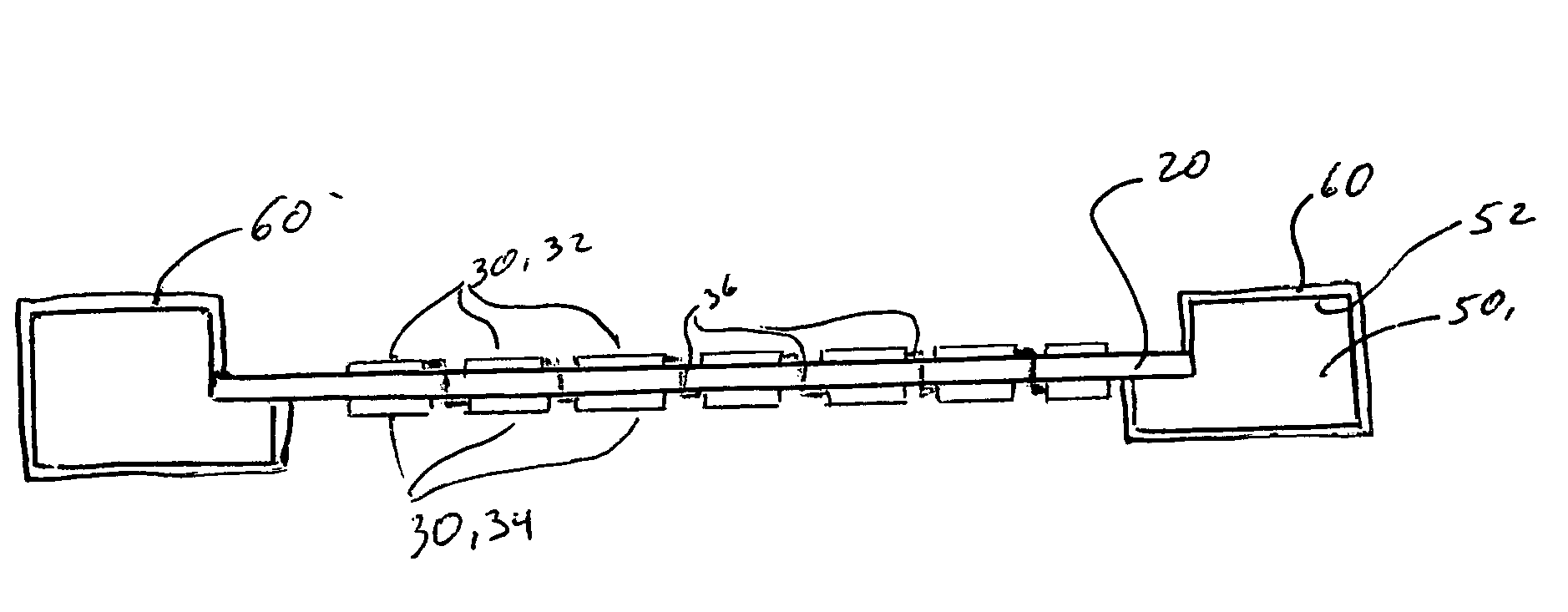
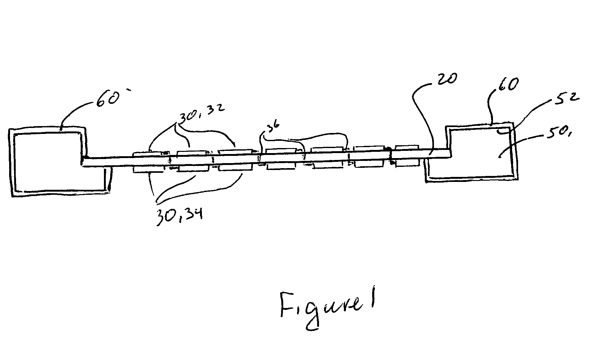
[0030] A solid oxide fuel cell device 10 shown in FIG. 1 includes: (a) yttria-stabilized zirconia (YSZ) electrolyte sheet 20; (b) a plurality of electrodes 30 situated on the electrolyte sheet 20, including at least one cathode 32; and (c) a metal frame 50 supporting the electrolyte sheet 20 and the electrodes 30 attached thereto. In this embodiment the electrolyte sheet 20 supports a plurality of cathode 32-anode 34 pairs and has a plurality of via holes filled with via interconnects 36.

[0031] It is preferable that the frame 50 and the electrolyte sheet 20 have similar coefficients of thermal expansion (CTE). Thus, because zirconia based electrolytes have a CTE of 11.4×10⁻⁶° C., it is preferable that the frame 50 has a CTE in the range of 10×10−6 / ° C. to 12.5×10⁻⁶ / ° C. It is more preferable that the CTE of the frame 50 be in the 11×10−6 / ° C. to 12×10−6 / ° C. range and most preferable that it is in 11.2×10⁻⁶ / ° C. to 11.7×10⁻⁶ / ° C. range. In this example the metal frame 50 is manufac...

example 2

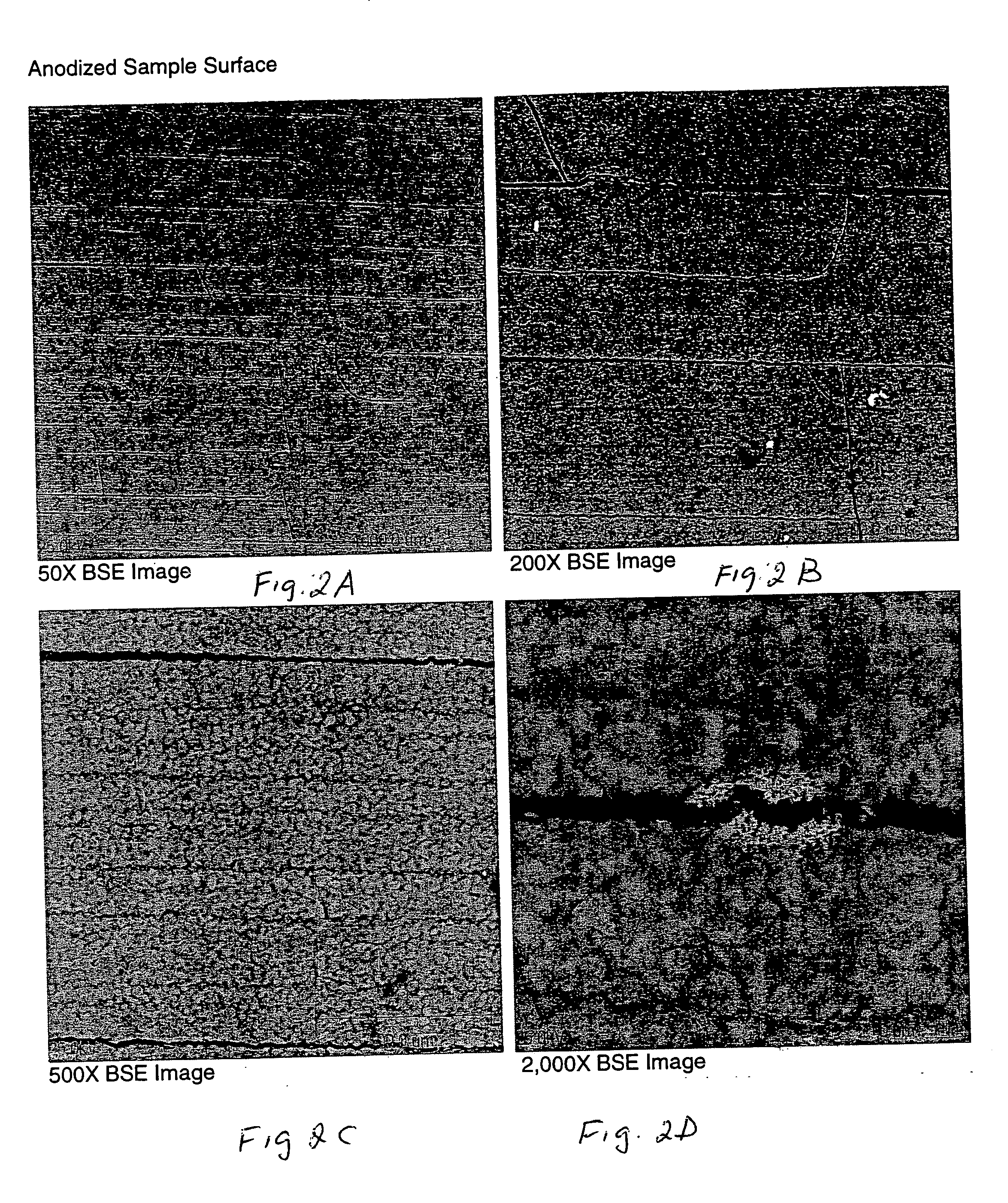
[0032] The aluminum oxide protective coating 60 may be produced by several methods. For example, it may be produced electrochemical oxidation of aluminum metal. Aluminum metal is first electrodeposited (using a nickel strike) on the component 50, for example stainless steel frame of example 1. An aluminum coating can be electroplated from inorganic and organic fused salt mixtures and from solutions of aluminum in certain organic solvents. Commercial aluminum electroplating services are available, for example, from AlumiPlate, Inc. of 8960 Springbrook Dr., Minneapolis, Minn. 55433-5874 USA.

[0033] In this example, a Ni strike was utilized to enable better aluminum coating of the 446 stainless steel. Subsequently, the aluminum (Al) coating is electrochemically oxidized (anodized) to aluminum oxide. Alternatively, aluminum oxide coating may be created by electroplating and subsequent thermal oxidation of Al coating. Whereas anodizing is typically associated with aluminum, similar proce...


PUM


Abstract

A solid oxide fuel cell device comprises: (a) zirconia based electrolyte; (b) at least one ectrode situated on the electrolyte; (c) a component situated in close proximity to the electrolyte, the component comprising at least one metal or metal oxide capable, at temperatures of above 625° C., of: (i) migrating to the surface of this component, and (ii) being re-deposited on said at least one electrode; and (d) a protective coating situated on at least one surface of this component. The protective coating substantially prevents the at least one metal or metal oxide from leaving the surface of the component, which is situated under said protective coating. The protective coating is also being substantially impermeable to oxygen.

Description

BACKGROUND OF THE INVENTION [0001] 1. Field of the Invention [0002] The present invention relates generally to coatings on metal components that are suitable for use in fuel cell devices, and particularly to protective coatings on stainless steel frames for supporting electrolytes in solid oxide fuel cell devices. [0003] 2. Technical Background [0004] The use of solid oxide fuel cells has been the subject of considerable amount of research in recent years. The typical components of a solid oxide fuel cell (SOFC) comprise a negatively-charged oxygen-ion conducting electrolyte sandwiched between two electrodes. Electrical current is generated in such cells by oxidation, at the anode, of a fuel material, for example hydrogen, which reacts with oxygen ions conducted through the electrolyte. Oxygen ions are formed by reduction of molecular oxygen at the cathode. [0005] It is known that substrate type solid oxide fuel cells sometimes utilize metal alloys as separators. Such configuration ...

Claims


Application Information

Patent Timeline
IPC IPC(8): H01M8/02H01M8/12
CPCH01M8/021H01M8/0273Y02E60/525H01M2008/1293Y02E60/521H01M8/1226Y02P70/50Y02E60/50
Inventor BADDING, MICHAEL E.KALAL, PETER J.WUSIRIKA, RAJA R.
Owner CORNING INC
Why Eureka
Try Eureka