
Super high density module with integrated wafer level packages

a technology of integrated circuits and wafers, applied in the direction of electrical equipment, semiconductor devices, semiconductor/solid-state device details, etc., can solve the problems of low profile products, small electronic products such as pages and cellular telephones, and small product sizes, so as to achieve low profile, increase memory capacity, and high memory capacity

Inactive Publication Date: 2005-03-03
MICRON TECH INC
View PDF60 Cites 45 Cited by
  • Summary
  • Abstract
  • Description
  • Claims
  • Application Information

AI Technical Summary

Benefits of technology

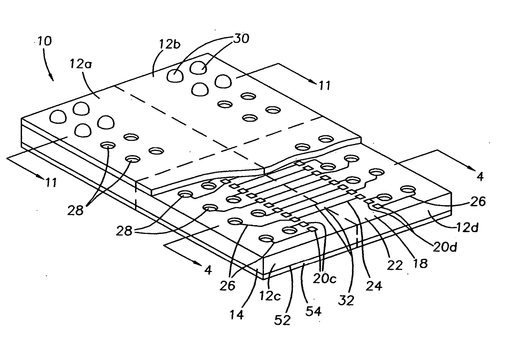
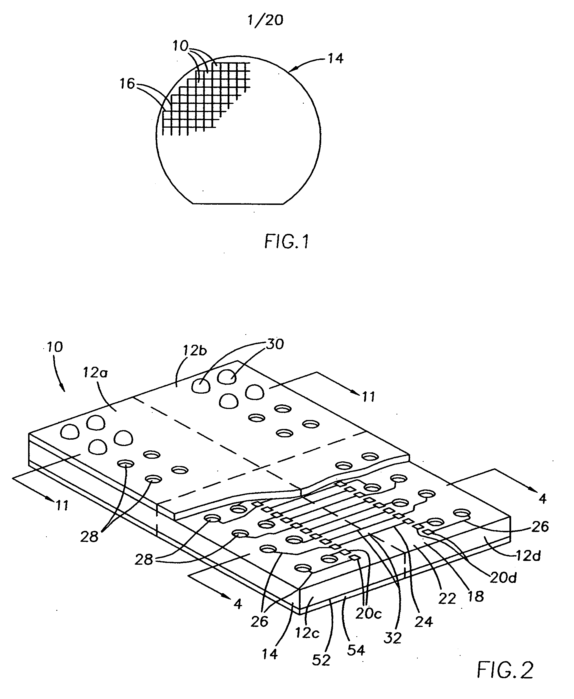
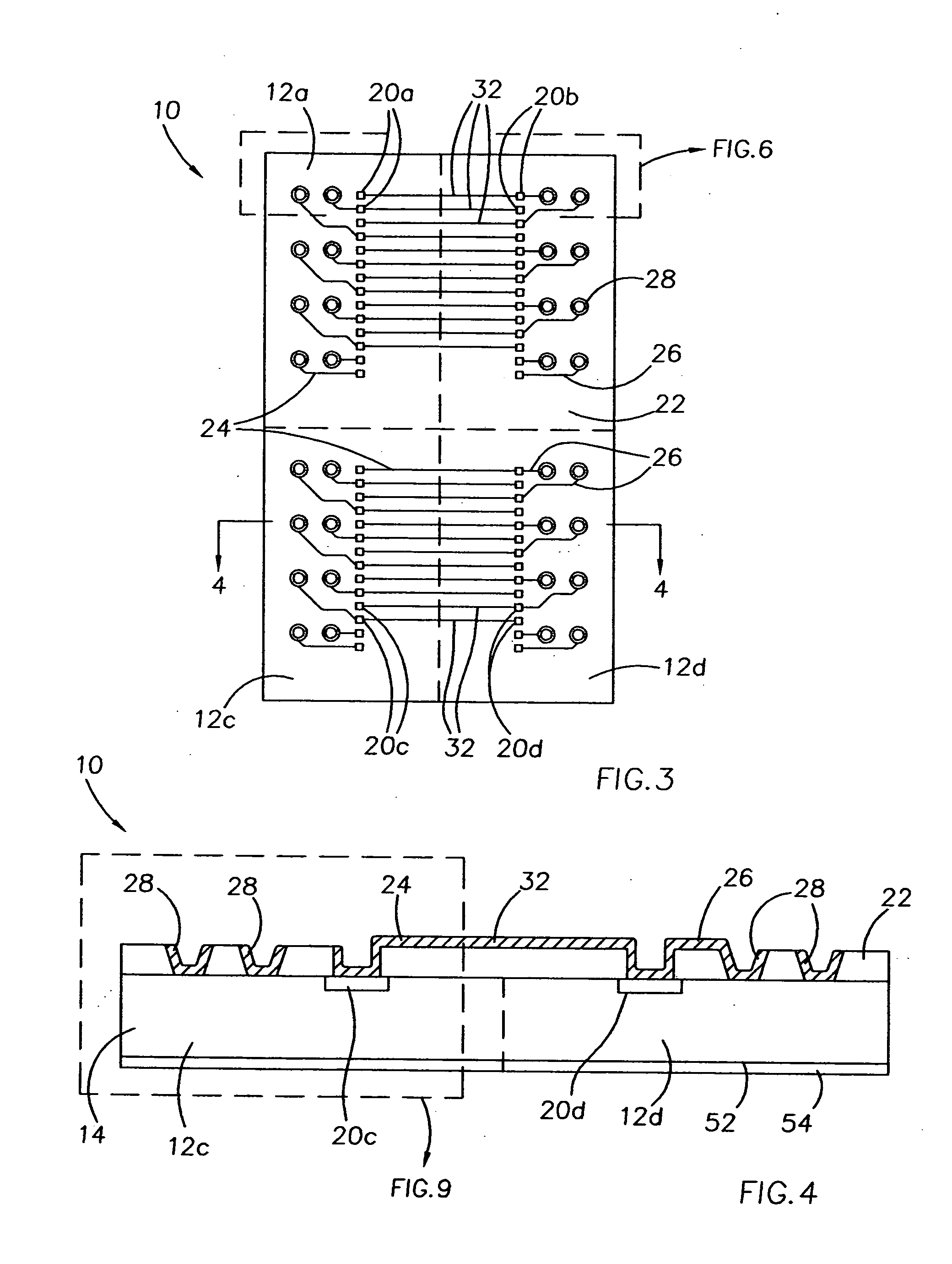
[0020] The present invention provides a multiple die package having an exceptionally high memory capacity with a low profile. The die package achieves a single unit (die package) having an increased memory capacity using current memory chips by virtue the interconnections between two or more chips within the package, without having to wait for the availability of the next higher density chip. The integrated wafer package also has the advantage of space saving on a module board due to the compact and thin profile, which in turn allows more integrated units / packages and higher memory capacity on the flip chip memory module such as a SIMM or DIMM board. The die package also provides superior signal integrity.
[0021] The configuration of the RDL with traces connecting bond pads of two or more dies together and routing the connection to a single ball pad also eliminates the need for a separate pin or ball contact for each individual bond pad, resulting in a lower pin count compared to other memory module chip units. The package also is easier to lay out on a DIMM board or or other memory module since part of the routing is done on a wafer level.

Problems solved by technology

However, a profusion of small electronic products such as pages and cellular telephones demand small product size and low profile products.

Method used


Image

  • Super high density module with integrated wafer level packages
  • Super high density module with integrated wafer level packages
  • Super high density module with integrated wafer level packages

Examples


Embodiment Construction

[0063] The invention will be described generally with reference to the drawings for the purpose of illustrating embodiments only and not for purposes of limiting the same. The figures illustrate processing steps for use in fabricating semiconductor devices in accordance with the present invention. It should be readily apparent that the processing steps are only a portion of the entire fabrication process.

[0064] In the current application, the terms “semiconductive wafer fragment” or “wafer fragment” or “wafer” will be understood to mean any construction comprising semiconductor material, including but not limited to bulk semiconductive materials such as a semiconductor wafer (either alone or in assemblies comprising other materials thereon), and semiconductive material layers (either alone or in assemblies comprising other materials). The term “substrate” refers to any supporting structure including, but not limited to, the semiconductive wafer fragments or wafers described above. ...


PUM


Abstract

A wafer level package, and a semiconductor wafer, electronic system, and a memory module that include one or more of the wafer level packages, and methods of fabricating the die packages on a wafer level, and integrated circuit modules that include one or more packages are provided. In one embodiment, the die package comprises a redistribution layer interconnecting two or more dies disposed on a substrate, typically a semiconductor wafer, the redistribution layer including a first trace connecting a bond pad of each of two dies, and a second trace connecting one of the bond pads of the two dies to a ball pad. The die package of the invention can comprise memory devices such as static random access memories (SRAMs), and can be incorporated into a variety of electronic systems as part of a memory package such as single in line memory modules (SIMMs) or dual in line memory modules.

Description

CROSS-REFERENCE TO RELATED APPLICATION [0001] This application is a divisional of U.S. patent application Ser. No. 10 / 167,284, filed Jun. 11, 2002, which claims priority to Singapore Patent Application No. 200203050-0, filed May 21, 2002.FIELD OF THE INVENTION [0002] This invention relates generally to integrated circuit chip packages, and more specifically to a method of forming an integrated circuit package at a wafer level. BACKGROUND OF THE INVENTION [0003] With the increase in memory needed by software, the trend in state-of-the-art microprocessors is toward higher performance, high-density memory modules, such as single in-line memory modules (SIMMs) or dual in-line memory modules (DIMMs), which are circuit cards with memory chips attached. Having higher capacity memory chip units or packing more memory chip units on a memory module is one way to increase memory density on a module. [0004] Conventional methods of mounting multiple die units on a module is through stacking the ...

Claims


Application Information

Patent Timeline
IPC IPC(8): H01L23/31H01L23/525H01L23/538H01L25/065
CPCH01L23/3114H01L23/525H01L24/13H01L23/5389H01L24/10H01L25/0655H01L2224/13099H01L2924/01013H01L2924/01022H01L2924/01029H01L2924/01073H01L2924/01074H01L2924/01078H01L2924/01079H01L2924/01082H01L2924/14H01L2924/01005H01L2924/01023H01L2924/01024H01L2924/01033H01L2924/014H01L2924/00H01L24/02H01L24/03H01L24/05H01L2224/02379H01L2224/05001H01L2224/05024H01L2224/05026H01L2224/05124H01L2224/05147H01L2224/05166H01L2224/05169H01L2224/05181H01L2224/05184H01L2224/05548H01L2224/05624H01L2224/05644H01L2224/05647H01L2224/05655H01L2224/0615H01L2224/13H01L2224/13024H01L2924/0001H01L2924/00014H01L2224/02
Inventor CHIA, YONG POOBOON, SUAN JEUNGLOW, SIU WAFNEO, YONG LOOSER, BOK LENG
Owner MICRON TECH INC
Learn More