Devices and methods for crossing a chronic total occlusion

a total occlusion and device technology, applied in the direction of dilators, catheters, guide wires, etc., can solve the problems of more difficult to cross chronic total occlusions, damage to the heart, and serious medical consequences, so as to increase the pitch, increase the tendency to expand, and maximize the torque transmission properties

Active Publication Date: 2005-03-03
ST JUDE MEDICAL CARDILOGY DIV INC +1
View PDF62 Cites 153 Cited by
  • Summary
  • Abstract
  • Description
  • Claims
  • Application Information

AI Technical Summary

Benefits of technology

[0014] In another embodiment, the catheter comprises an elongate tubular member having a proximal region, a distal region, and a lumen extending therebetween. A multilayer torque cable is disposed in the proximal region of the elongate tubular member. The multilayer torque cable includes a first helical coil and a second helical coil. The first helical coil is nested within the second helical coil and wound in a reverse direction from the second helical coil. Rotation of the first helical coil in a first direction causes the first helical coil to expand while rotation of the second helical coil in the first direction causes the second helical coil to compress and thereby interfere with the expansion of the first helical coil. A third helical coil surrounding the second helical coil may be included in certain embodiments. The catheter further includes a monolayer helical coil in the distal region of the elongate tubular member. An outer jacket surrounds the monolayer helical coil to restrict expansion on rotation of the monolayer helical coil. Any one or more of the first helical coil, the second helical coil, the third helical coil, and the monolayer helical coil may be multifilar. Multifilar construction increases the pitch between coil windings, thereby increasing the tendency to expand on rotation, thereby maximizing the torque transmission properties.
[0016] In use, a catheter as described herein is provided to the physician. The catheter comprises an elongate tubular member having a proximal region, a distal region, and a lumen extending therebetween. The catheter further has a multilayer torque cable in the proximal region of the elongate tubular member as described above. The catheter further includes a monolayer helical coil in the distal region of the elongate tubular member and an outer jacket surrounding the monolayer helical coil to restrict expansion on rotation of the monolayer helical coil. The catheter is advanced to a region of interest e.g., in an artery proximal to a lesion.
[0020] In still another embodiment, a catheter is provided comprising a proximal handle, a torque cable extending distally from the proximal handle, and an outer jacket extending distally from the proximal handle. The outer jacket surrounds the torque cable with an annular gap disposed between the torque cable and the outer jacket. The annular gap allows the torque cable to rotate independently of the outer jacket for at least a portion of the length of the catheter.
[0021] The torque cable may be a multilayer torque cable comprising a first helical coil and a second helical coil. When this is the case, the first helical coil is nested within the second helical coil and wound in a reverse direction from the second helical coil. Rotation of the first helical coil in a first direction causes the first helical coil to expand while rotation of the second helical coil in the first direction causes the second helical coil to compress and thereby interfere with the expansion of the first helical coil, resulting in torsional stiffness. Any one or more of the first helical coil and the second helical coil may be multifilar. Multifilar construction increases the pitch between coil windings, thereby increasing the tendency to expand on rotation, thereby maximizing the torque transmission properties. The catheter may further include a balloon mounted on the distal region of the catheter, the balloon defining a chamber that communicates with the annular gap as an inflation lumen.
[0022] In use, a catheter as described above is provided to the physician. The catheter comprises a proximal handle, a torque cable extending distally from the proximal handle, and an outer jacket extending distally from the proximal handle and surrounding the torque cable. An annular gap is disposed between the torque cable and the outer jacket. The catheter is advanced to a region of interest in the artery proximal a lesion. Torque is applied to the proximal handle. The torque is transmitted through the torque cable with the outer jacket remaining stationary for at least a portion of its length. The annular gap allows the torque cable to rotate independently of the outer jacket.

Problems solved by technology

Such blockages can have serious medical consequences, depending upon their location within a patient's vascular system.
For example, blockage of the coronary vessels that supply blood to the heart can cause damage to the heart.
Chronic total occlusions are more difficult to cross than partially occluded lesions because a guidewire must penetrate the lesion, rather than navigate a pre-existing lumen.
Complications may result from these difficulties.
For example, the distal end and tip of the guidewire may have insufficient support or rigidity to enter the lesion, causing the end to buckle.
If the guidewire has a pre-formed bend at the tip to assist in its initial orientation as it enters the occlusion, the internal lesion tissue may cause the guidewire to take an unwanted path within the occlusion.
If the guidewire cannot successfully cross the occlusion, subsequent therapeutic devices, such as a balloon angioplasty catheter, cannot be advanced across the occlusion to dilate and treat it.
Similar problems are encountered when attempting to cross an occlusion at a bifurcation.
A guidewire having insufficient support or rigidity to enter the lesion will bend or, in some cases, perforate the vessel at the bifurcation.
Furthermore, even when the total occlusion is successfully crossed with conventional guidewires, it often requires a great deal of time and skill on the part of the physician.

Method used


Image

  • Devices and methods for crossing a chronic total occlusion
  • Devices and methods for crossing a chronic total occlusion
  • Devices and methods for crossing a chronic total occlusion

Examples


Embodiment Construction

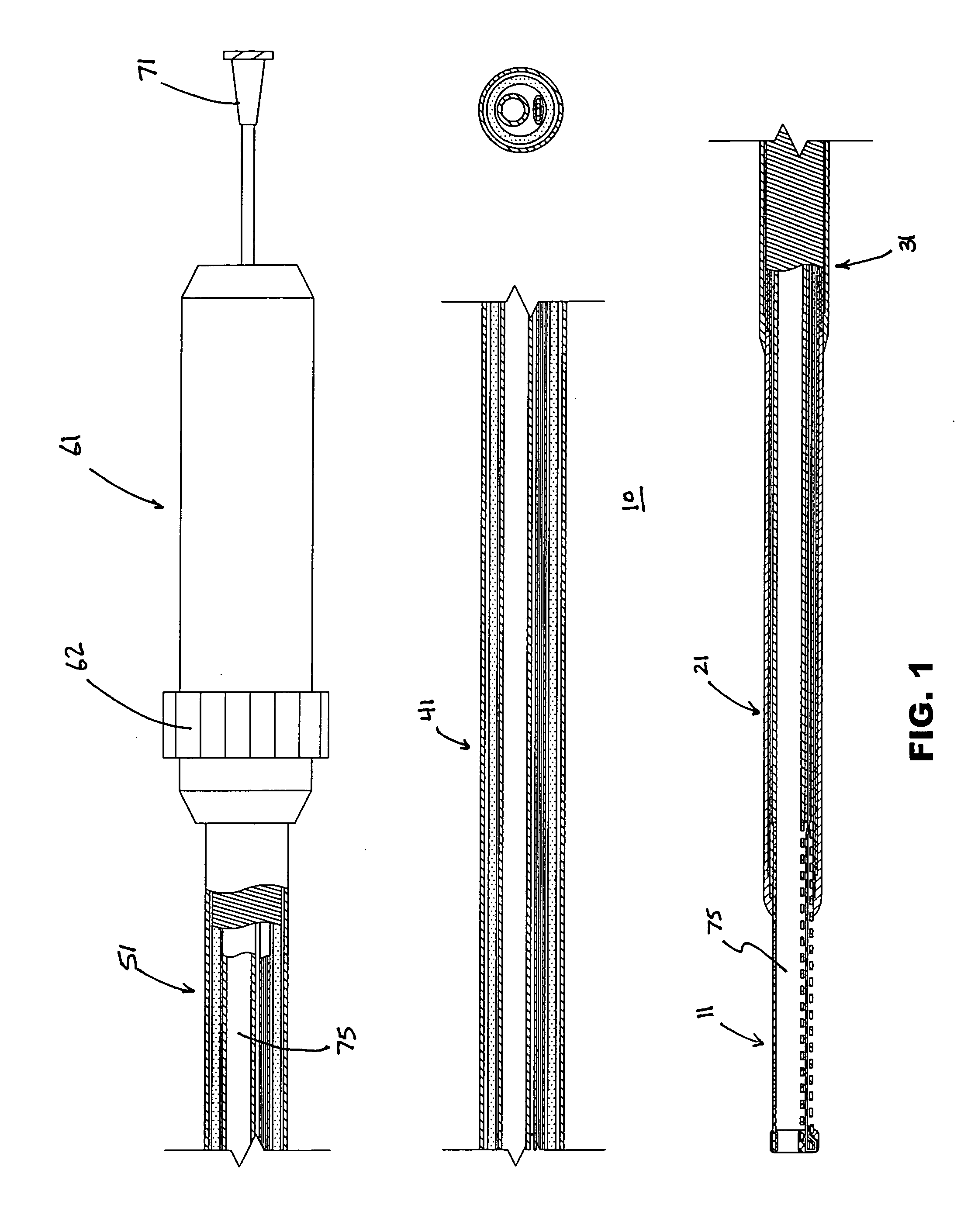
[0047] A first embodiment of articulating tip catheter 10 is illustrated in FIG. 1. This embodiment includes a variably deflectable tip region 11, a distal shaft region 21, a transition region 31, a main shaft region 41, a handle 61, and lumen 75 communicating with luer 71. The handle is described in further detail later, but is secured to the main shaft region to provide torquing and tip deflection input to the catheter.

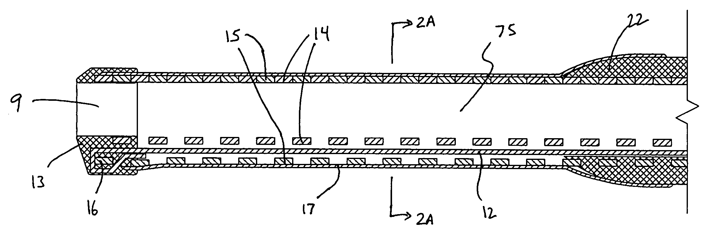
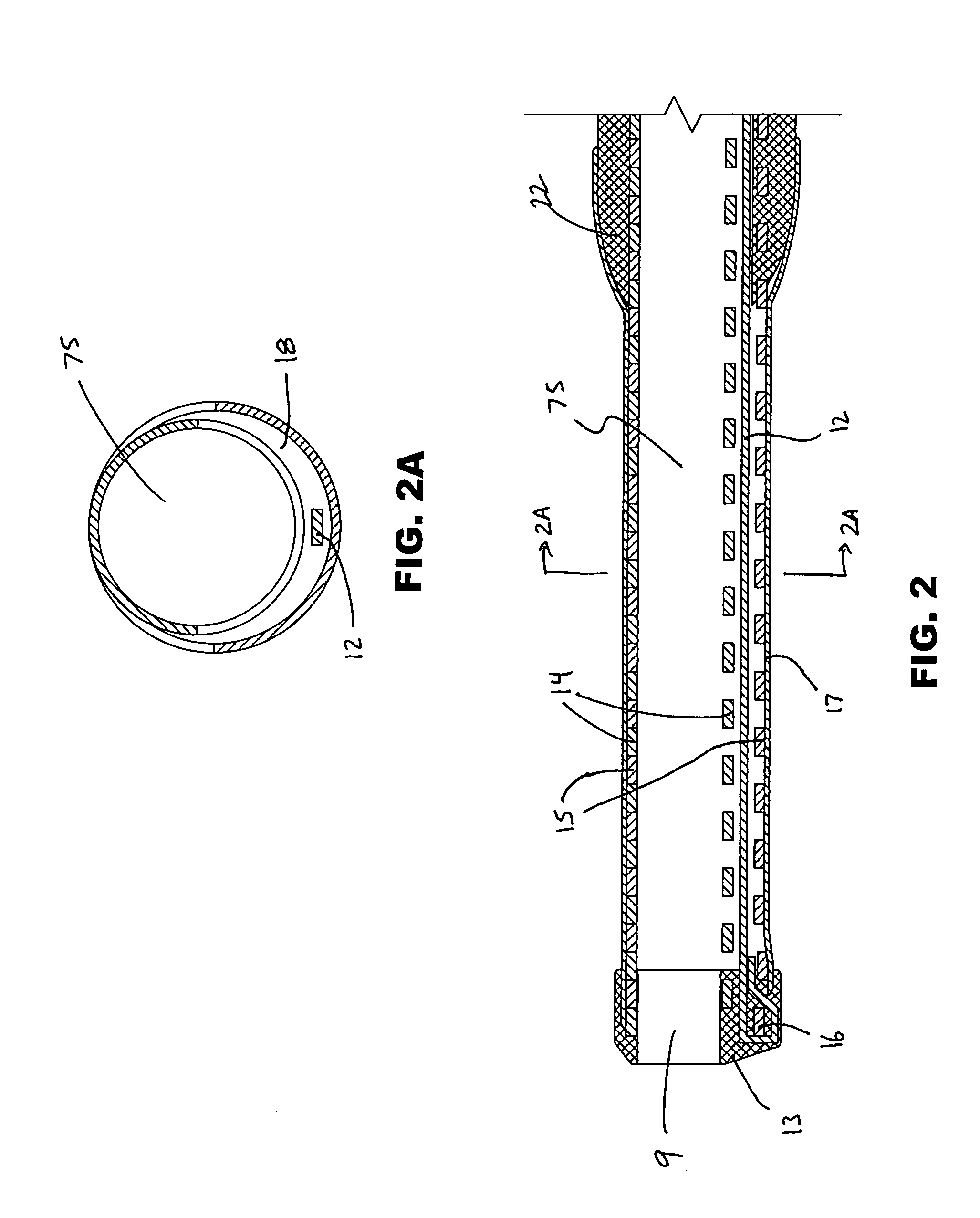
[0048]FIG. 2 illustrates one embodiment of the deflectable tip region. An articulation structure is shown comprising two coils wound to two different diameters nested together, i.e., a smaller diameter inner coil 14, and a larger diameter outer coil 15. Control wire 12 is secured to distal end 13 of the articulation structure, by forming a loop in the control wire which surrounds the distal-most turn 16 of the outer coil. The control wire may be further secured to the coil structure by means of a spot weld. When the control wire is moved proximally relative to the ...


PUM

PropertyMeasurementUnit
deflection angleaaaaaaaaaa
lengthaaaaaaaaaa

Abstract

A catheter comprising an elongate tubular member having a proximal end and a distal end, and a deflectable tip at the distal end of the elongate tubular member. The deflectable tip comprises a first helical coil having a first diameter and a second helical coil having a second diameter, the first diameter being larger than the second diameter. The first and second helical coils are arranged in the manner of a double helix. When viewed in cross-section, the first helical coil and the second helical coil are aligned at a first point on a circumference of each coil and misaligned at a second point on the circumference of each coil, where the second point is approximately 180 degrees from the first point. In certain embodiments the catheter further includes a dilatation balloon. Methods of use for crossing a chronic total occlusion are also described.

Description

FIELD OF THE INVENTION [0001] The present invention relates to apparatus and methods used to cross lesions in blood vessels, and in more particular embodiments, catheters for controlling a guidewire to cross a chronic total occlusion in a blood vessel. BACKGROUND [0002] Chronic Total Occlusions (CTOs) are vascular lesions which are totally occluded and thereby inhibit normal blood flow. Such occlusions can occur anywhere in a patient's vascular system, arteries, and veins, including coronary vessels, as well as carotid arteries, renal arteries, cerebral arteries, arteries of the head and neck, iliac arteries, femoral arteries, popliteal arteries, and other peripheral arteries. [0003] Typically, a CTO may be occluded for several weeks to several months, or longer. Such blockages can have serious medical consequences, depending upon their location within a patient's vascular system. For example, blockage of the coronary vessels that supply blood to the heart can cause damage to the he...

Claims


Application Information

Patent Timeline
Patent Type & Authority Applications(United States)
IPC IPC(8): A61F2/958A61MA61M25/00A61M25/01A61M31/00
CPCA61M25/0026A61B2017/22094A61M25/005A61M25/0052A61M25/0053A61M25/0068A61M25/0069A61M25/008A61M25/0108A61M25/0136A61M25/0138A61M25/0147A61M25/02A61M25/104A61M2025/0081A61M2025/015A61M2025/09191A61M2025/1079A61B2017/22044A61M25/0045
Inventor PETRICK, TIMOTHY B.WILLARD, STEVEN N.KEITH, PETER T.WAHR, DENNIS W.
Owner ST JUDE MEDICAL CARDILOGY DIV INC
Why Eureka
Try Eureka