
Devices and methods for the production of particles

Inactive Publication Date: 2005-03-10
UNIV OF COLORADO THE REGENTS OF
View PDF13 Cites 32 Cited by
  • Summary
  • Abstract
  • Description
  • Claims
  • Application Information

AI Technical Summary

Benefits of technology

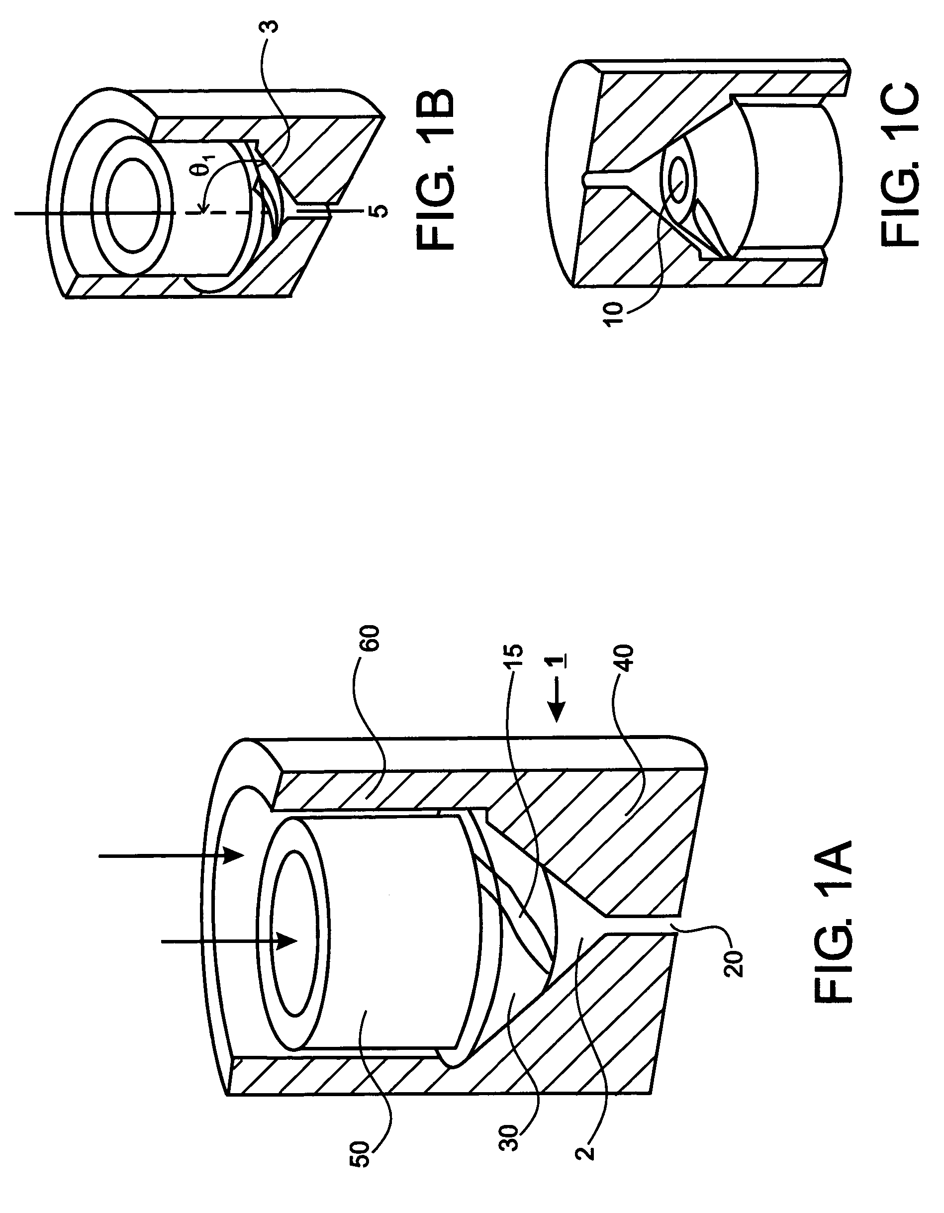
The present invention provides methods and devices for producing particles with an average diameter of less than about 15 microns. The particles can be produced using the PCA process o

Problems solved by technology

However these techniques have limitations that include excessive solvent use, thermal and chemical degradation of the solute, large residual solvent concentrations, and difficulties in controlling particle size and size distribution during processing.
These limitations may affect powder stability, flow properties, and delivery efficiency (P. H. Hirst, et al.
Overall, the production of monodisperse powders with a controlled particle size in the micro / nanoscale remains challenging.
In addition, various process parameters such as temperature, pressure, solute concentration, and solvent / solute flow rate have been manipulated to adjust particle size, but the results show there is a limited range in polymer size variation when these process parameters are varied.
Overall, manipulation of particle size distributions has proved difficult using conventional PCA mixing configurations.
Based on these results, liquid atomization theory and Weber number based analysis are no longer considered the appropriate theory and parameter to characterize the process.
However, the ultrasonic horns are expensive and have a limited life time at high pressure.
Furthermore, heat is an unknown and uncontrolled variable.
Furthermore, this process has not been demonstrated for polymer particles.
The authors state that large-scale inhomogeneity may still exist in the flow through the nozzle.
Although nanoscale particles have been made using the PCA and CAN-BD processes, the resulting particle size distributions have not always been optimal.

Method used


Image

  • Devices and methods for the production of particles
  • Devices and methods for the production of particles
  • Devices and methods for the production of particles

Examples


examples

Formation of Poly(l-lactide Particles with the PCA Process

Poly (l-lactide) (PLA) was purchased from Birmingham Polymers, Inc. (Birmingham, Ala.) and used as received. The reported average molecular weight was 100,000. Methylene chloride (HPLC grade) and isopropyl alcohol were purchased from Fischer Scientific (Pittsburgh, Pa.), and medical grade carbon dioxide was obtained from United States Welding Inc. (Denver, Colo.).

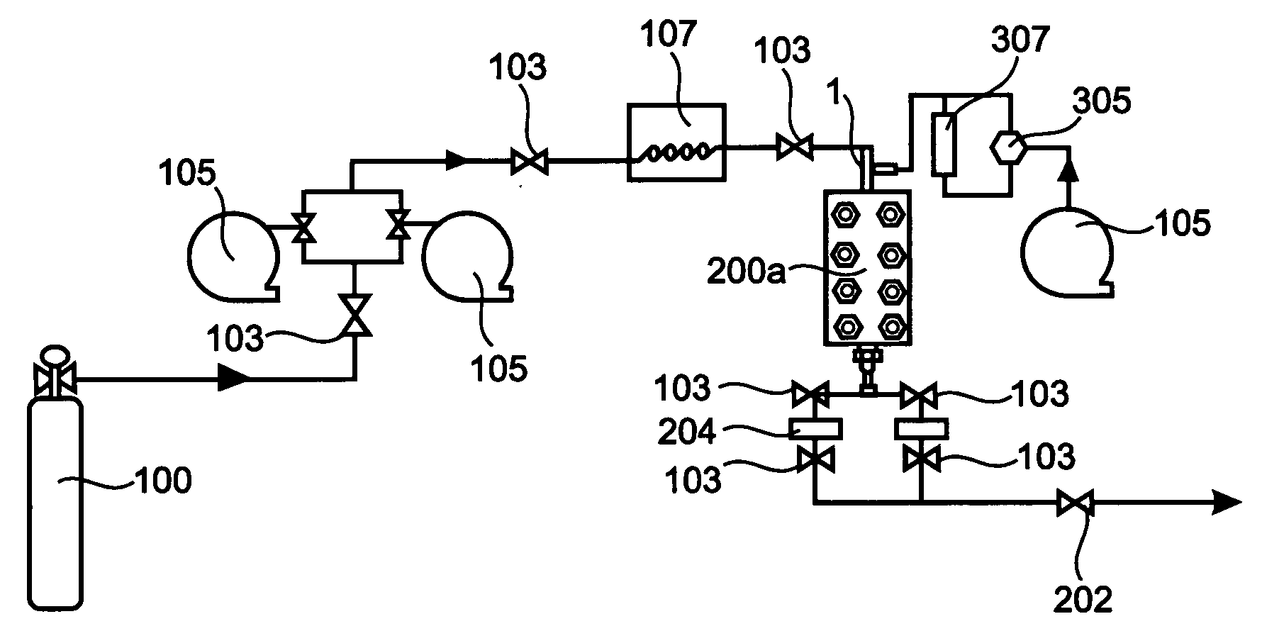
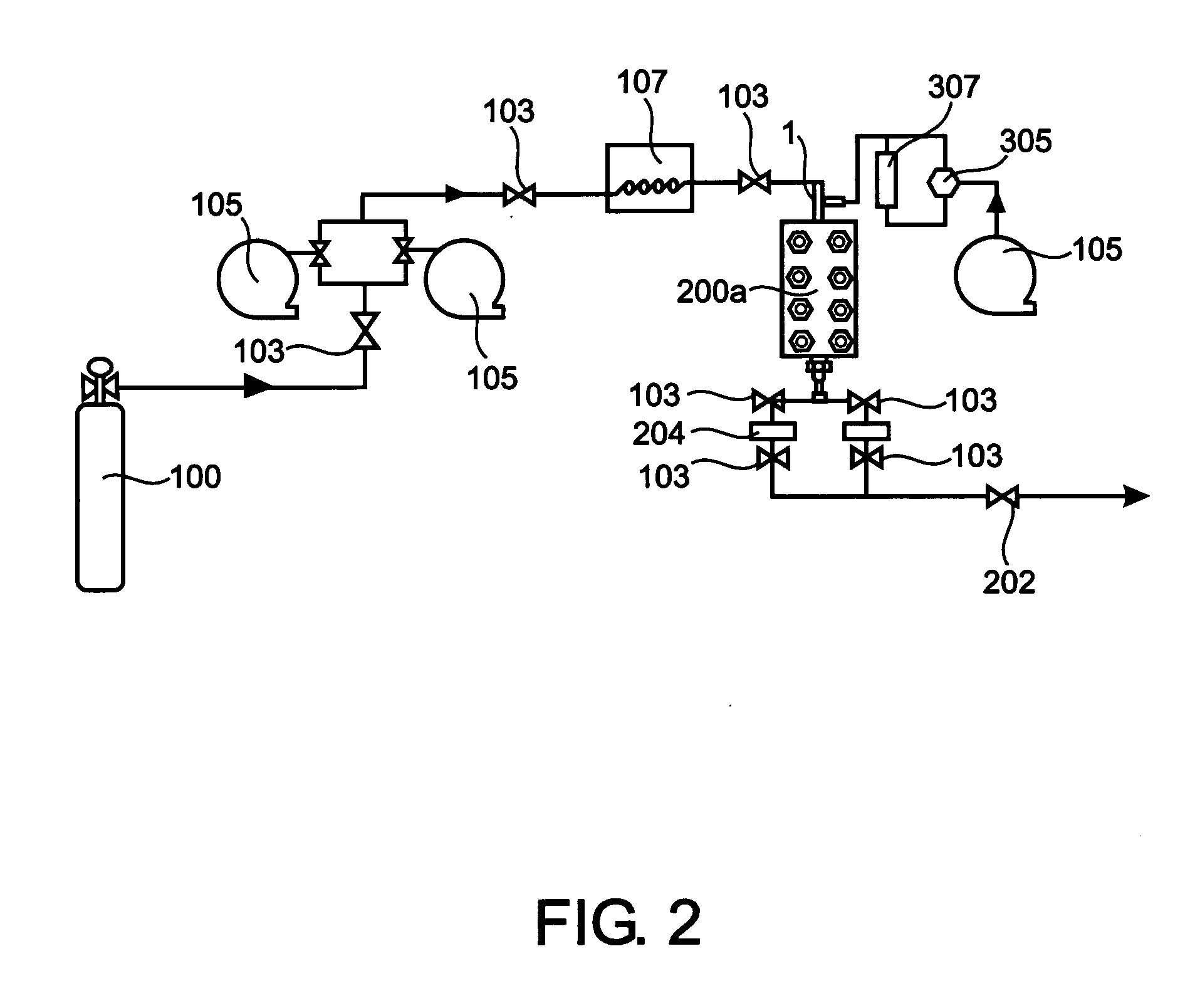
The experimental apparatus used to perform the PCA process in a semi-continuous fashion is shown in FIG. 2. Carbon dioxide from a gas supply cylinder (100) was fed into two ISCO model 260D syringe pumps (105) that were chilled by ethylene glycol jackets to −12° C. The ISCO pumps were controlled by an ISCO series D pump controller. Liquid carbon dioxide was then reheated to 35° C. by a water bath (107) prior to entering the nozzle and then the particle formation vessel. Valves (103) are also shown. The particle formation vessel (200a) consisted of a high-pressure...


PUM

PropertyMeasurementUnit
Lengthaaaaaaaaaa
Angleaaaaaaaaaa
Diameteraaaaaaaaaa

Abstract

The present invention provides methods and devices for producing particles with an average diameter less than about 15 μm using the precipitation with compressed fluid-antisolvent (PCA) process and the carbon-dioxide assisted nebulization with a bubble dryer (CAN-BD) process. In the methods and nozzles of the invention, at least one jet of supercritical or near-supercritical fluid and at least one jet of solution interact to mix the supercritical or near-supercritical fluid and the solution within a chamber. The solution contains at least one solvent and at least one solute. At least one of the jets is a swirling jet. To form particles, the solvent and supercritical or near-supercritical fluid are then injected into a PCA or a CAN-BD process chamber. The degree of mixing depends in part on the power input into the mixing chamber. Power inputs of about 6.5×10⁹ W / m3 enhance the degree of mixing and allow production of nanoscale particles with the PCA process. The nanoscale particles have a size distribution so that polydispersity is less than about 1.75.

Description

BACKGROUND OF THE INVENTION This invention is in the field of particles having an average diameter less than about 15 microns, and in particular is directed to methods and devices for making particles using the precipitation with compressed-fluid antisolvent (PCA) process and the carbon-dioxide assisted nebulization with a bubble dryer (CAN-BD) process. Dry powder formulations with a controlled particle size and size distribution have many applications in the field of pharmaceutical drug delivery, especially in the areas of pulmonary delivery, controlled release, and needle-less powder injections. These formulations require precise control of particle size and size distribution. For example, pulmonary dosage forms of solid particles require particle diameters of about 1-3 μm in order to effectively target regions of the deep lung (J. Heyder et al. (1986) J. Aerosol Sci. 5:811). There has been considerable interest in developing polymeric nanoparticles (about 1-100 nm) that allow f...

Claims


Application Information

Patent Timeline
IPC IPC(8): B01D11/04B01F5/00B01J2/04
CPCB01F5/0057B01F2003/0064B01D11/0407B01J2/04B01D11/0403B01D11/0473B01F23/043B01F25/10
Inventor GROTHE, WILLYJARMER, DANIELLENGSFELD, CORINNERANDOLPH, THEODORE
Owner UNIV OF COLORADO THE REGENTS OF
Learn More