Device for monitoring blood flow to brain

a blood flow and brain technology, applied in the field of medical instruments, can solve the problems of inability to accurately measure brain blood flow, so as to reduce motion artifacts

Inactive Publication Date: 2005-03-10
ORSAN MEDICAL TECH
View PDF36 Cites 127 Cited by
  • Summary
  • Abstract
  • Description
  • Claims
  • Application Information

AI Technical Summary

Benefits of technology

[0009] An aspect of some embodiments of the invention relates to using impedance measurements of at least part of the head to estimate blood flow to the brain. For some applications, it is not necessary to measure the absolute impedance accurately, since the blood flow is estimated, and/or the presence of significant blood flow is ascertained, by observing changes in the impedance (due to changes ...

Problems solved by technology

There is a need to measure cerebral blood flow during several medical events and procedures, because any disturbance to the flow of blood to the brain may cause an injury to the function of the brain cells, and even death of brain cells if the disturbance is prolonged.
Existing means for measuring cerebral blood flow are complex, expensive, and in some cases invasive, which limits their usefulness.
Three non-portable methods that are presently used only in research are: 1) injecting radioactive xenon into the cervical carotid arteries and observing the radiation it emits as it spreads throughout the brain; 2) positron emission tomography, also based on the injection of radioactive material; and 3) magnetic resonance angiography, performed using a room-sized, expensive, magnetic resonance imaging system, and requiring several minutes to give results.
How...

Method used


Image

  • Device for monitoring blood flow to brain
  • Device for monitoring blood flow to brain
  • Device for monitoring blood flow to brain

Examples


Embodiment Construction

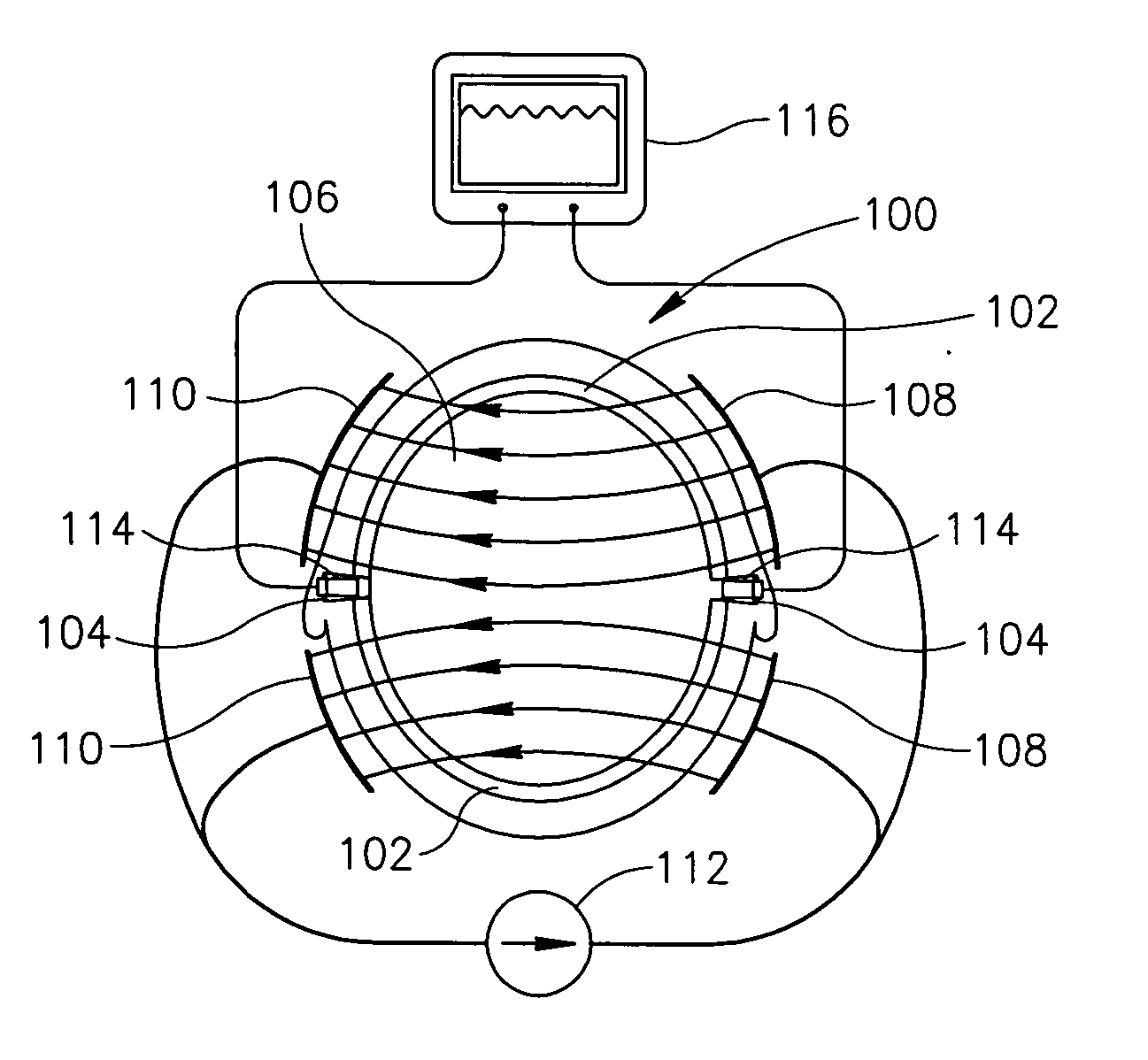
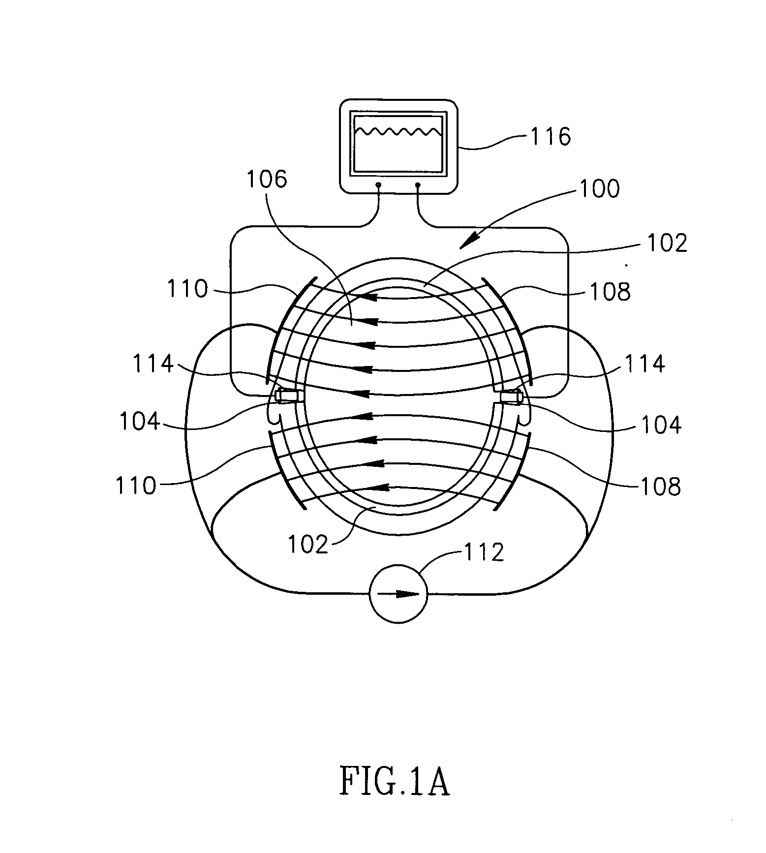
[0090]FIG. 1 shows a cross-section of a head 100 seen from the top, including a skull 102 with two openings 104 associated with the ears, and an interior region 106 which includes the brain. It is desired to measure changes in the electrical impedance of interior region 106, without having the measurements dominated by the much greater impedance of the skull. Two positive current-carrying electrodes 108 are shown in contact with the skin on the right side of the head, one in front of the ear and one behind the ear. Similarly, two negative current-carrying electrodes are shown in contact with the skin on the left side of the head. This may be varied, for example there is only one electrode on each side, or there are more than two electrodes on each side, or the electrodes are above or below the ears, or on the ears, and the number of positive electrodes need not equal the number of negative electrodes. Having a large area of the cranium, for example 2% or 5% or 10% or more of the sur...


PUM


Abstract

A method of estimating blood flow in the brain, comprising: a) causing currents to flow inside the head by producing electric fields inside the head; b) measuring at least changes in the electric fields and the currents; and c) estimating changes in the blood volume of the head, using the measurements of the electric fields and the currents.

Description

RELATED APPLICATION [0001] The present application is a continuation in part of PCT Application No. PCT / IL03 / 00042, filed on Jan. 15, 2003. The present application also claims the benefit under § 119(e) of U.S. Provisional Application No. 60 / 348,278, filed on Jan. 15, 2002. The disclosures of these applications are incorporated herein by reference.FIELD OF THE INVENTION [0002] The field of the invention is medical instrumentation, for example for measuring blood flow to the brain. BACKGROUND OF INVENTION [0003] There is a need to measure cerebral blood flow during several medical events and procedures, because any disturbance to the flow of blood to the brain may cause an injury to the function of the brain cells, and even death of brain cells if the disturbance is prolonged. Maintaining blood flow to the brain is especially important because brain cells are more vulnerable to a lack of oxygen than other cells, and because brain cells usually cannot regenerate following an injury. A...

Claims


Application Information

Patent Timeline
IPC IPC(8): A61B5/026A61B5/0265A61B5/04A61B5/053
CPCA61B5/0261A61B5/0265A61B5/04008A61B2562/164A61B5/6814A61B5/6817A61B5/0535A61B5/0295A61B5/245
Inventor BEN-ARI, SHLOMIRAPPAPORT, ALONSHAPIRA, AHARON
Owner ORSAN MEDICAL TECH
Why Eureka
Try Eureka