Flexible display panel method

Inactive Publication Date: 2005-03-17
3GI TECH
View PDF5 Cites 0 Cited by
  • Summary
  • Abstract
  • Description
  • Claims
  • Application Information

AI Technical Summary

Benefits of technology

[0009] Much of this art is based on the encapsulated cathode ray tube to protect the screen elements from environmental exposure and resulting damage. The envelope is necessary to: (i) hold the gasses required to create discharge boundaries within the tube and outward to the responding phosphorus pixels; (ii) maintain a rigid framework for the screen; and (iii) provide a safety barrier from vacuum tube implosion. Although new, more responsive materials have been developed for displays, the basic design in the art is maintained because of the

Problems solved by technology

Although new, more responsive materials have been developed for displays, the basic design in the art is maintained because of the higher manufacturing costs required by the new concepts.
The metals used in the art,

Method used


Image

  • Flexible display panel method
  • Flexible display panel method
  • Flexible display panel method

Examples


Embodiment Construction

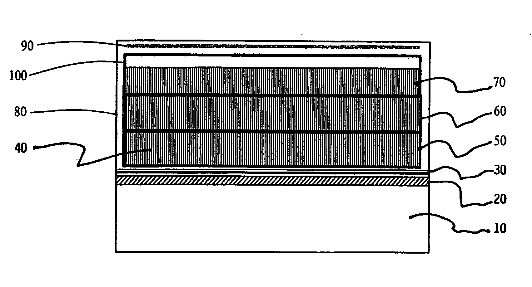
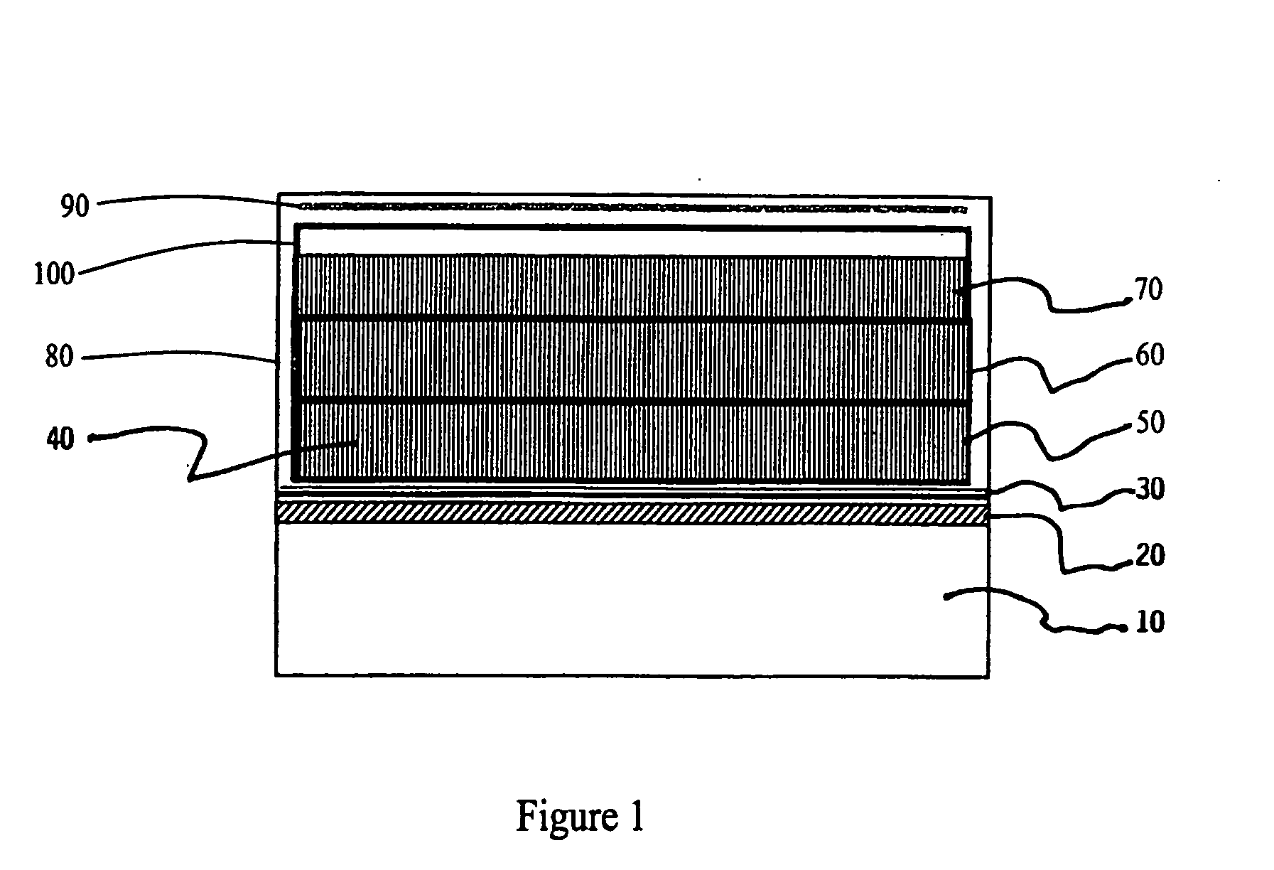
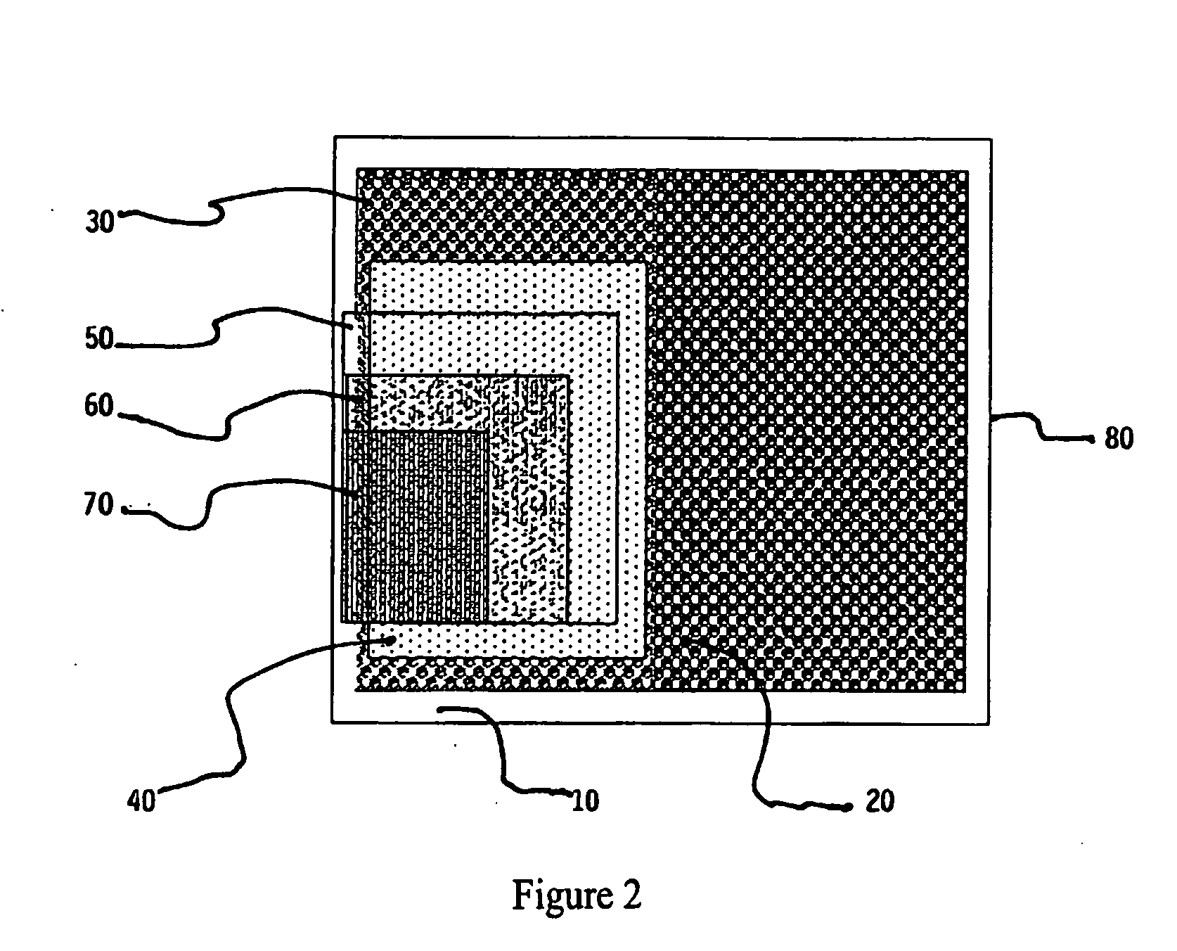
[0031] The flexible panel display of the present invention provides use of the novel single point, three-color pixel with increased resolution of over sixty (60%) percent over display in the art. As depicted in FIGS. 1 and 2, the panel of the preferred embodiment of the present invention comprises a polyester film substrate, similar to the product sold under the mark Mylar® or polymer substrate 10 which is coated with a driver transistor matrix 20, a gold conductive layer 30, micro carbon fiber emitters 40, three light emitting polymer layers 50, 60, and 70, each having a field charge overcoat 100, and finally an encapsulation layer 80 that serves as the outer protective casing of the panel, including the panel faceplate and backplate.

[0032] The substrate 10 functions as an insulator and support base for the matrix structure and panel membranes which are layered upon the substrate surface. It is also the back surface of the panel display. The substrate 10 is also the supporting mem...


PUM


Abstract

A method of constructing a flexible panel display using gold as a conductive element and a matrix of carbon fibers as emitters is presented. The invention provides a novel defined pixel width of three emitter fibers per cell wherein each cell is positioned within three emulsion layers of suspended nano-crystals stack positioned vertically atop one-another. Each of these respective layers is excited by a single carbon fiber. In the preferred embodiment, fiber length ends from each cell are positioned at the mid-point of each respective polymer layer thickness and produce one of red, green, or blue colors required to complete the image formation.

Description

CROSS-REFERENCES TO RELATED APPLICATIONS [0001] This patent application is a divisional application of previously filed and pending U.S. non-provisional application Ser. No. 10 / 230,598 filed on Aug. 29, 2002, as allowed under 35 U.S.C. §121.STATEMENT REGARDING FEDERALLY SPONSORED RESEARCH OR DEVELOPMENT [0002] None. REFERENCE TO A MICRO-FICHE APPENDIX [0003] None. BACKGROUND OF THE INVENTION [0004] 1. Field of the Invention [0005] The present invention relates to a method of constructing a flexible panel display which uses gold as a conductive element and a matrix of carbon fibers as emitters. The invention provides a novel defined pixel width of three emitter fibers per cell. Each solo dot or cell is positioned within three emulsion layers of suspended nano-crystals stack positioned vertically atop one-another with each of these respective layers being excited by a single fiber from each cell. Each fiber length end is positioned at the mid-point of each respective polymer layer thi...

Claims


Application Information

Patent Timeline
IPC IPC(8): C09K11/65H01J1/304H01J1/63H01J1/70H01J31/12
CPCB82Y20/00C09K11/06C09K11/65H01J31/12H01J1/3048H01J1/63H01J1/70H01J1/3044
Inventor ELLIS, ALAN D.
Owner 3GI TECH
Why Eureka
Try Eureka