
A corrugated substrate-porous metal self-heating methanol reforming hydrogen production reactor

A porous metal, reforming hydrogen production technology, applied in the direction of non-metallic elements, hydrogen, chemical instruments and methods, etc., can solve the problem of reducing the dynamic response speed and mass power density of the system, without considering the reaction rate and catalyst requirements, reactors The thickness of the substrate and other issues can be reduced to reduce the start-up and response time, reduce structural redundancy, and reduce thermal resistance.

Active Publication Date: 2021-01-15
ZHEJIANG UNIV
View PDF13 Cites 0 Cited by
  • Summary
  • Abstract
  • Description
  • Claims
  • Application Information

AI Technical Summary

Problems solved by technology

[0008] However, the structure of the self-heating methanol steam reforming reactor that has been disclosed so far does not take into account the difference in reaction rate and catalyst requirements between the methanol steam reforming reaction and the methanol catalytic combustion reaction, and there is structural redundancy. At the same time, the substrate of the reactor thicker, the heat capacity of the reactor is large, which reduces the dynamic response speed and mass power density of the system

Method used


Image

  • A corrugated substrate-porous metal self-heating methanol reforming hydrogen production reactor
  • A corrugated substrate-porous metal self-heating methanol reforming hydrogen production reactor
  • A corrugated substrate-porous metal self-heating methanol reforming hydrogen production reactor

Examples


Embodiment Construction

[0035] The present invention will be further described below in conjunction with the accompanying drawings and embodiments.

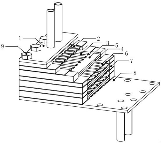
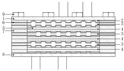
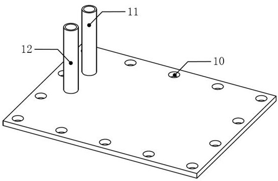
[0036] Such as figure 1 , figure 2 As shown, the reactor of the present invention includes an upper cover plate 1 sequentially from top to bottom, a corrugated substrate with multiple sets of convex arrays with the same structure stacked upwards and convex arrays downwards, and two stacked porous metal plates. Structural unit, the lower cover plate 8, graphite gaskets 7 are placed around the adjacent plates, and the bolt holes 10 around each plate are connected into a whole with fastening bolts 9; The evaporation chamber 2 is formed between the cover plates 1, and the first methanol catalytic combustion chamber is formed in the corrugated substrate with the convex array upward and the convex array downward, and the corrugated substrate with the convex downward and the convex upward is welded on it The first methanol water vapor reforming chamber is f...


PUM

PropertyMeasurementUnit
densityaaaaaaaaaa
densityaaaaaaaaaa
thicknessaaaaaaaaaa

Abstract

The invention discloses a corrugated substrate-porous metal self-heating methanol reforming hydrogen production reactor. The reactor comprises an upper cover plate, a plurality of groups of corrugatedsubstrates which are of the same structure and have upward overlaying bulge arrays and downward overlaying bulge arrays, a structural unit with two laminated porous metal plates and a lower cover plate, wherein graphite gaskets are arranged between adjacent substrates, an evaporation chamber is formed by the first group of corrugated substrate with upward overlaying bulge arrays and an upper cover plate, and a first methanol catalytic combustion chamber is formed in each corrugated substrate with upward overlaying bulge arrays and downward overlaying bulge arrays; a first methanol water vaporreforming chamber is formed between the two porous metal plates, and by that analogy, a last methanol catalytic combustion chamber and a last methanol water vapor reforming chamber are formed. Through different design of the combustion chambers and the reforming chambers, the compactness and power density of the reactor structure are improved; the distribution uniformity of reactants is improvedthrough the corrugated substrates, and the catalyst loading and coating area can be improved through the porous metal plates; and light weight is achieved through the light-weight corrugated substrates and the porous metal structure, and the dynamic response speed of the reactor is improved.

Description

technical field [0001] The invention relates to a methanol reforming hydrogen production reactor, in particular to a corrugated substrate-porous metal self-heating methanol reforming hydrogen production reactor. [0002] technical background [0003] Since the 21st century, the rigid growth of energy demand and the two-way pressure of energy conservation and emission reduction have forced human beings to seek and develop clean and renewable new energy sources. Among the existing new energy sources, hydrogen energy has the advantages of high combustion calorific value, low pollution, and renewable energy, and is expected to become an ideal alternative energy source for fossil fuels. [0004] Hydrogen fuel cells are one of the main ways to utilize hydrogen energy. A fuel cell is a device that can directly convert chemical energy into electrical energy. It is not limited by the Carnot cycle. The energy conversion efficiency is higher than that of traditional thermal power gener...

Claims


Application Information

Patent Timeline
Patent Type & Authority Patents(China)
IPC IPC(8): C01B3/32
CPCB01J2219/00018B01J2219/00121B01J2219/2428C01B3/326C01B2203/0233C01B2203/0811C01B2203/1035C01B2203/1082C01B2203/1223
Inventor 梅德庆洪子越汪延成易邹东一
Owner ZHEJIANG UNIV
Learn More