Solid oxide fuel cell and manufacturing method thereof

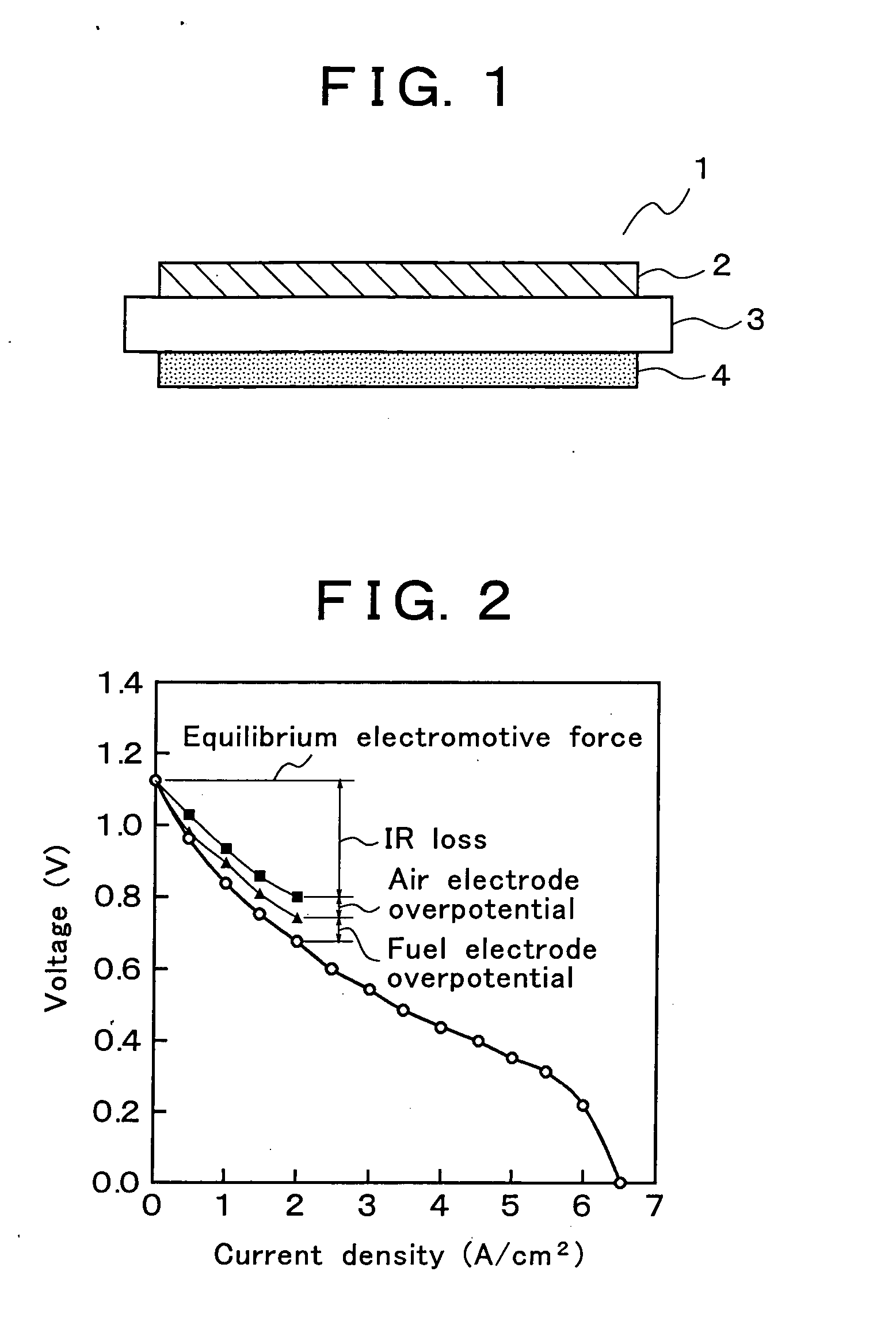
a solid oxide fuel cell and manufacturing method technology, applied in the direction of cell components, final product manufacturing, sustainable manufacturing/processing, etc., can solve the problems of ir loss, voltage drop with increasing irreversibility, etc., to reduce the overpotential of each electrode and ir loss, and improve the efficiency of electric power generation

Inactive Publication Date: 2005-03-24
THE KANSAI ELECTRIC POWER CO +2
View PDF4 Cites 5 Cited by
  • Summary
  • Abstract
  • Description
  • Claims
  • Application Information

AI Technical Summary

Benefits of technology

[0021] The configurations and the manufacturing methods according to the present invention as recited in claims 1 to 4 reduce the overpotential of each electrode and the IR loss, and accordingly improve the electric power generation efficiency.

Problems solved by technology

Because the air electrode material is required to be chemically stable in the oxidative atmosphere at high temperatures around 700° C., metals are unsuitable for the air electrode, and generally used are perovskite type oxide materials having electronic conductivity, specifically LaMnO3, LaCoO3 and the solid solutions in which part of the La component in these materials is replaced with Sr, Ca and the like.
The maximum voltage obtainable in an actual fuel cell is the equilibrium electromotive force and the voltage falls with increasing irreversibility.
Incidentally, in a fuel cell, in order to raise the voltage to be taken out, a cell stack is used in which a number of electric power generation cells (single cells) are jointed in series with interconnectors; however, in this case the electric resistance of the interconnectors themselves also causes the IR loss.

Method used


Image

  • Solid oxide fuel cell and manufacturing method thereof
  • Solid oxide fuel cell and manufacturing method thereof

Examples


examples

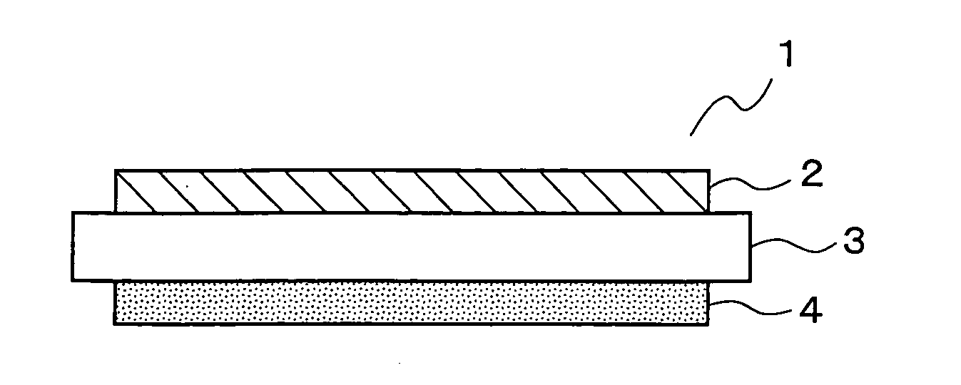
[0032] Step 1: Fabrication of a Solid Electrolyte Layer

[0033] As source materials, La2O3, SrCO3, Ga2O3, MgO, and CoO were prepared, weighed out in predetermined amounts, subjected to mixing with the aid of a ball mill, heated in air at 1,200° C. for calcination, and additionally pulverized with the aid of a ball mill, and thus a lanthanum gallate based oxide powder was produced. The lanthanum gallate based oxide powder thus obtained was molded into a thin plate shape with the aid of a method well known in the art such as the doctor blade method and the like, and then heated at 1,450° C. in air; thus the solid electrolyte material plates (Examples 1 to 4) of the compositions and thickness values shown in Table 1 were manufactured.

[0034] Step 2: Production of the Fuel Electrode Layer

[0035] In each of the present Examples, the fuel electrode layer was produced by the spray thermal decomposition method described below.

[0036] Nickel nitrate, cerium nitrate and samarium nitrate were p...


PUM

PropertyMeasurementUnit
average primary grain sizeaaaaaaaaaa
temperatureaaaaaaaaaa
temperaturesaaaaaaaaaa

Abstract

An electric power generation cell 1 is constituted by arranging a fuel electrode layer 4 on one side of a solid electrolyte layer 3 and an air electrode layer 2 on the other side of the solid electrolyte layer 3. The solid electrolyte layer 3 is constituted of an oxide ion conductor mainly composed of a lanthanum gallate based oxide. The fuel electrode layer 4 is constituted of a porous sintered compact having a highly dispersed network structure in which a skeletal structure formed of a consecutive array of metal grains is surrounded by mixed conductive oxide grains. For the air electrode layer 2, a porous sintered compact mainly composed of cobaltite is used. This configuration reduces the overpotentials of the respective electrodes and the IR loss of the solid electrolyte layer 3, and accordingly can actualize a solid oxide type fuel cell excellent in electric power generation efficiency.

Description

TECHNICAL FIELD [0001] The present invention relates to a solid oxide fuel cell which is provided with the electric power generation cell constituted by arranging a fuel electrode layer on one side of a solid electrolyte layer and an air electrode layer on the other side of the solid electrolyte layer, in particular, to reduction of the electrode overpotential (polarization) in an electric power generation cell of the fuel cell. BACKGROUND OF THE INVENTION [0002] Development of the solid electrolyte type fuel cell having a laminated structure for which the solid electrolyte layer composed of an oxide ion conductor is sandwiched between an air electrode layer (oxidant electrode layer) and a fuel electrode layer is progressing as the fuel cell for use in the next (third) generation electric power production. In a solid electrolyte type fuel cell, oxygen (air) is supplied to an air electrode section and a fuel gas (H2, CO, and the like) is supplied to a fuel electrode section. Both the...

Claims


Application Information

Patent Timeline
Patent Type & Authority Applications(United States)
IPC IPC(8): C01G15/00C01G51/00H01M4/86H01M4/88H01M8/02H01M8/12
CPCH01M4/8621H01M4/8885H01M4/9033Y10T29/49108H01M8/1246Y02E60/521Y02E60/525H01M4/9066Y02E60/50Y02P70/50
Inventor INAGAKI, TORUYOSHIDA, HIROYUKISASAKI, TSUNEHISAMIURA, KAZUHIROFUKUI, TAKEHISAOHARA, SATOSHIHOSOI, KEIHOSHINO, KOJIADACHI, KAZUNORI
Owner THE KANSAI ELECTRIC POWER CO
Why Eureka
Try Eureka