Method of manufacturing semiconductor devices
a semiconductor and manufacturing method technology, applied in the field of semiconductor devices, can solve the problems of inability to apply constitution to the pixel tft, increase of off current, etc., and achieve the effect of suppressing preventing an increase in off current, and preventing deterioration of on curren
- Summary
- Abstract
- Description
- Claims
- Application Information
AI Technical Summary
Benefits of technology
Problems solved by technology
Method used
Image

Examples
example 1
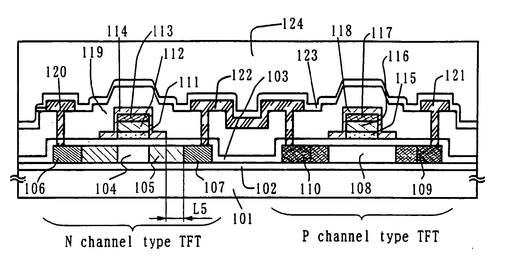
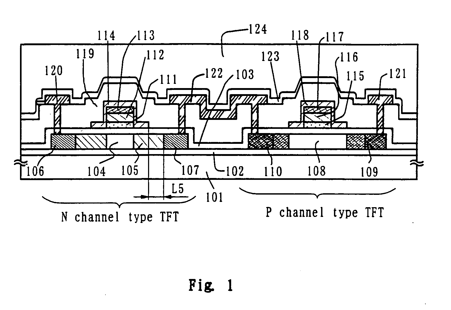
[0088] This example describes a constitution of this invention, a method of manufacturing simultaneously a pixel area and CMOS circuits that are basic configuration of driving circuits provided around the pixel area.
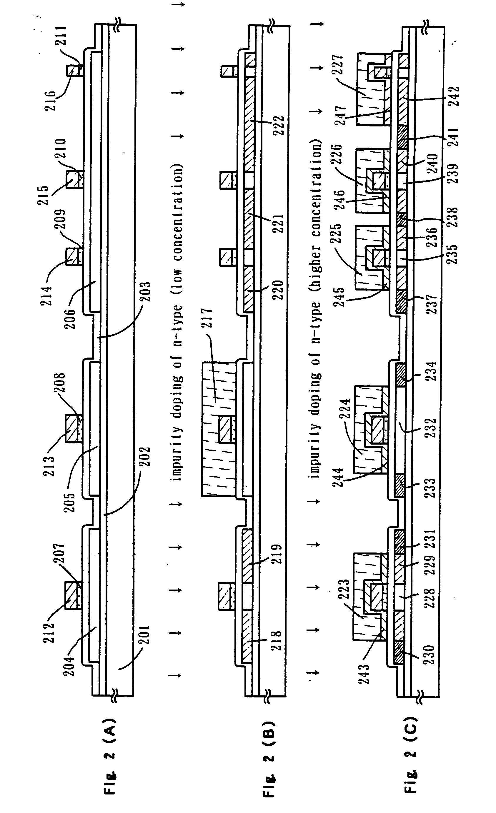
[0089] In FIG. 2, a substrate 201 is an alkali-free glass substrate, represented, for example, by 1737 glass substrate of Corning make. The surface of the substrate 201 where the TFT is to be formed is deposited with a base film 202 made mainly of silicon oxide to a thickness of 200 nm. The base film 202 may use a silicon nitride film or silicon oxynitride film.
[0090] The base film 202 may be formed in a single layer of the material above or in two or more layers. In either case, it is formed to a thickness of about 100 to 300 nm. For example, the base film 202 may be formed by a plasma CVD method as a two-layer constitution, in which a first silicon oxynitride film is formed from SiH4, NH3 and N2O to a thickness of 10 to 100 nm and a second silicon oxynitride film fro...
example 2
[0116] This example shows an example case where, after the state shown in FIG. 2(C) has been obtained by the same process as in the example 1, a part of the second conductive layer is removed by other method to form a region where the first impurity region overlaps the second conductive layer and a region where it does not.
[0117] First, as shown in FIG. 2(C), the resist masks 223, 224, 225, 226, 227 used in the process of patterning the second conductive layer are used as is to etch back a part of the second gate electrode by a length L5 as shown in FIG. 4(A).
[0118] This process was performed by dry etching. Depending on the material of the second conductive layer, a fluorine-based gas is basically used to achieve an isotropic etch and thereby remove those parts of the second conductive layer beneath the resist masks. The etching gas, for example, is a CF4 gas for Ta, a CF4 or CCl4 gas for Ti, and an SF6 or NF3 for Mo.
[0119] Then, as shown in FIG. 4(B), the second conductive laye...
example 3
[0121] This example describes a process of manufacturing an active matrix liquid crystal display from an active matrix substrate formed in the example 1 or example 2.
[0122] In the active matrix substrate as shown in FIG. 3(C) or FIG. 4(C), contact holes are formed in the second interlayer insulating film 270 to reach the drain line 268, and then a pixel electrode 271 is formed. The pixel electrode 271 uses a transparent conductive film for a transmission type liquid crystal display and a metal film for a reflection type liquid crystal display. Here, in order to fabricate a transmission type liquid crystal display, an indium-tin oxide (ITO) film is sputtered to a thickness of 100 nm to form the pixel electrode 271.
[0123] After the state of FIG. 5(A) is obtained, an alignment film 272 is formed over the second interlayer insulating film 270 and the pixel electrode 271. Generally, the alignment film for the liquid crystal display element often uses a polyimide resin. A counter substr...
PUM
 Abstract
Description
Claims
Application Information
 - R&D
- Intellectual Property
- Life Sciences
- Materials
- Tech Scout
- Unparalleled Data Quality
- Higher Quality Content
- 60% Fewer Hallucinations
Browse by: Latest US Patents, China's latest patents, Technical Efficacy Thesaurus, Application Domain, Technology Topic, Popular Technical Reports.
© 2025 PatSnap. All rights reserved.Legal|Privacy policy|Modern Slavery Act Transparency Statement|Sitemap|About US| Contact US: help@patsnap.com