
Lithographic printing plate precursor and lithographic printing method

a technology of lithographic printing plate and precursor, which is applied in thermography, instruments, photosensitive materials, etc., can solve the problems of insufficient printing durability, low image strength, and unfixed recording layer

Active Publication Date: 2005-04-07
FUJIFILM CORP
View PDF21 Cites 34 Cited by
  • Summary
  • Abstract
  • Description
  • Claims
  • Application Information

AI Technical Summary

Benefits of technology

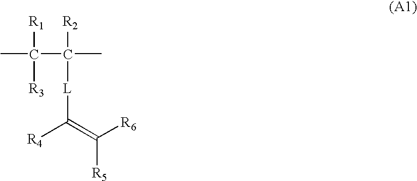
With respect to the manner in which the specific copolymer is used in the invention, it may be incorporated into the image-recording layer or may be incorporated into a layer adjacent to the image-recording layer, such as, e.g., an undercoat layer (interlayer) disposed between the support and the image-recording layer. However, it is especially preferred to use the copolymer in the undercoat layer because this enables the effects of the invention to be sufficiently produced. In this case, there is an advantage that since the undercoat layer functions as a heat-insulating layer, the heat generated by exposure with an infrared laser is prevented from diffusing to the support and is efficiently utilized, whereby enhanced sensitivity can be attained. In addition, this undercoat layer in unexposed areas facilitates the separation of the image-recording layer from the support to thereby improve on-press developability.

Problems solved by technology

However, in the case where the conventional image-recording method, which utilizes a light having wavelengths from the ultraviolet to visible region, is used for the simplification of a platemaking operation, such as on-press development, the image-recording layer remains unfixed after exposure and hence retains sensitivity to indoor light.
However, the technique described above in which an image is formed by the mere bonding of fine polymer particles by thermal fusion has been disadvantageous in that image strength is considerably low and printing durability is insufficient, although the lithographic printing plate precursor shows satisfactory on-press developability.
However, those techniques have been still insufficient from the standpoint of satisfying both of on-press developability and thin-line reproducibility or printing durability.

Method used


Image

  • Lithographic printing plate precursor and lithographic printing method
  • Lithographic printing plate precursor and lithographic printing method
  • Lithographic printing plate precursor and lithographic printing method

Examples


example 1

A methanol solution of a copolymer represented by Compound Example 4 (x / y=80 / 20; weight-average molecular weight, 15,000) was applied to the support produced above and then dried in an oven at 70° C. for 30 seconds to form an undercoat layer in an amount of 10 mg / m2 on a dry basis.

Subsequently, a coating fluid for image-recording layer formation which had the following composition was applied by bar coating and then dried in an oven at 70° C. for 60 seconds to form an image-recording layer in an amount of 0.8 g / m2 on a dry basis. Thus, a lithographic printing plate precursor was obtained.

Coating Fluid for Image-Recording Layer Formation (1)Water 100 gMicrocapsules (1) shown below (on solid basis)   5 gPolymerization initiator (1) shown below 0.5 gFluorochemical surfactant (1) shown below 0.2 g

(Synthesis of Microcapsules (1))

In 17 g of ethyl acetate were dissolved 10 g of a trimethylolpropane / xylene diisocyanate adduct (Takenate D-110N, manufactured by Mitsui Takeda Chemicals...

examples 2 to 8

Lithographic printing plate precursors were obtained in the same manner as in Example 1, except that each of the compounds shown in Table 1 was used in place of the copolymer represented by Compound Example 4.

TABLE 1CopolymerCopolymerization proportion (molar ratio),ExampleWeight-average molecular weightExample 28x / y = 40 / 60, Mw = 15000Example 319x / y / z = 40 / 30 / 30, Mw = 17000Example 422x / y = 60 / 40, Mw = 12000Example 531x / y / z = 30 / 30 / 40, Mw = 11000Example 643x / y = 70 / 30, Mw = 25000Example 750x / y / z = 30 / 40 / 30, Mw = 16000Example 855x / y / z = 20 / 40 / 40, Mw = 8000

example 9

A methanol solution of a copolymer represented by Compound Example 43 (x / y=80 / 20 (molar ratio); weight-average molecular weight, 25,000) was applied to the support produced above and then dried in an oven at 70° C. for 30 seconds to form an undercoat layer in an amount of 10 mg / m2 on a dry basis.

Subsequently, a coating fluid for image-recording layer formation which had the following composition was applied by bar coating and then dried in an oven at 100° C. for 60 seconds to form an image-recording layer in an amount of 1.0 g / m2 on a dry basis. Thus, a lithographic printing plate precursor was obtained.

Coating Fluid for Image-Recording Layer Formation (2)Infrared absorber (2) shown below0.05 gPolymerization initiator (1) shown above 0.2 gBinder polymer (1) shown below b 0.5 g(average molecular weight, 80,000)Polymerizable compound 1.0 gIsocyanuric acid EO-modified triacrylate(NK Ester M-315, manufactured byShin-Nakamura Chemical Co., Ltd.)Fluorochemical surfactant (1) shown ab...


PUM

PropertyMeasurementUnit
Areaaaaaaaaaaa
Hydrophilicityaaaaaaaaaa

Abstract

A lithographic printing plate precursor comprising: a support; and at least one layer comprising an image-recording layer, the image-recording layer comprising (A) an infrared absorber, (B) a polymerization initiator, (C) a polymerizable compound, and (D) a binder polymer, wherein the image recording layer is capable of being removed with at least one of a printing ink and a fountain solution, wherein at least one of said at least one layer comprises a copolymer having (a1) a unit comprising at least one ethylenically unsaturated bond, and (a2) a unit comprising at least one functional group interacting with a surface of the support. And a lithographic printing method in which the lithographic printing plate precursor is used. The copolymer preferably has a hydrophilic segment. The copolymer preferably is contained in an undercoat layer formed between the support and the image-recording layer.

Description

BACKGROUND OF THE INVENTION 1. Field of the Invention The present invention relates to a lithographic printing plate precursor and a lithographic printing method for using the same. More particularly, the invention relates to a lithographic printing plate precursor of the so-called direct platemaking type, from which a printing plate can be directly obtained through scanning with an infrared laser based on digital signals from, e.g., a computer. The invention further relates to a lithographic printing method in which the lithographic printing plate precursor is developed on a printing machine and used to conduct printing. 2. Description of the Related Art A lithographic printing plate generally has ink-receptivity image areas, which receive an ink during printing, and hydrophilic non-image areas, which receive a fountain solution. Lithography is a process in which the surface of a lithographic printing plate is made to have a difference in ink adhesion by forming ink-receptivity...

Claims


Application Information

Patent Timeline
IPC IPC(8): B41C1/10G03F7/004B41M5/36B41N1/08B41N1/14G03F7/00G03F7/11
CPCB41C1/1016B41M5/368B41N1/083B41C1/1008B41C2201/02B41C2201/04B41C2210/24B41C2201/14B41C2210/04B41C2210/08B41C2210/20B41C2210/22B41C2201/12
Inventor MAKINO, NAONORIINNO, TOSHIFUMIYAMASAKI, SUMIAKI
Owner FUJIFILM CORP
Learn More