Method and system for patterning of magnetic thin films using gaseous transformation

Active Publication Date: 2005-04-14
IBM CORP
View PDF25 Cites 30 Cited by
  • Summary
  • Abstract
  • Description
  • Claims
  • Application Information

AI Technical Summary

Benefits of technology

[0013] In view of the foregoing and other exemplary problems, drawbacks, and disadvantages of the conventional methods and structures, an exemplary feature of the present inventio

Problems solved by technology

However, prior to the invention, such a technique has not been applied to magnetic memory devices.
Mainly, the failure of the final product is due to non-uniformity of magnetic switching properties in the potentially millions of junctions on a memory chip.
Also, edge roughness is known to cause variation due to edge pinning of magnetization.
Thus, ion-beam patterning (as opposed

Method used


Image

  • Method and system for patterning of magnetic thin films using gaseous transformation
  • Method and system for patterning of magnetic thin films using gaseous transformation
  • Method and system for patterning of magnetic thin films using gaseous transformation

Examples


Embodiment Construction

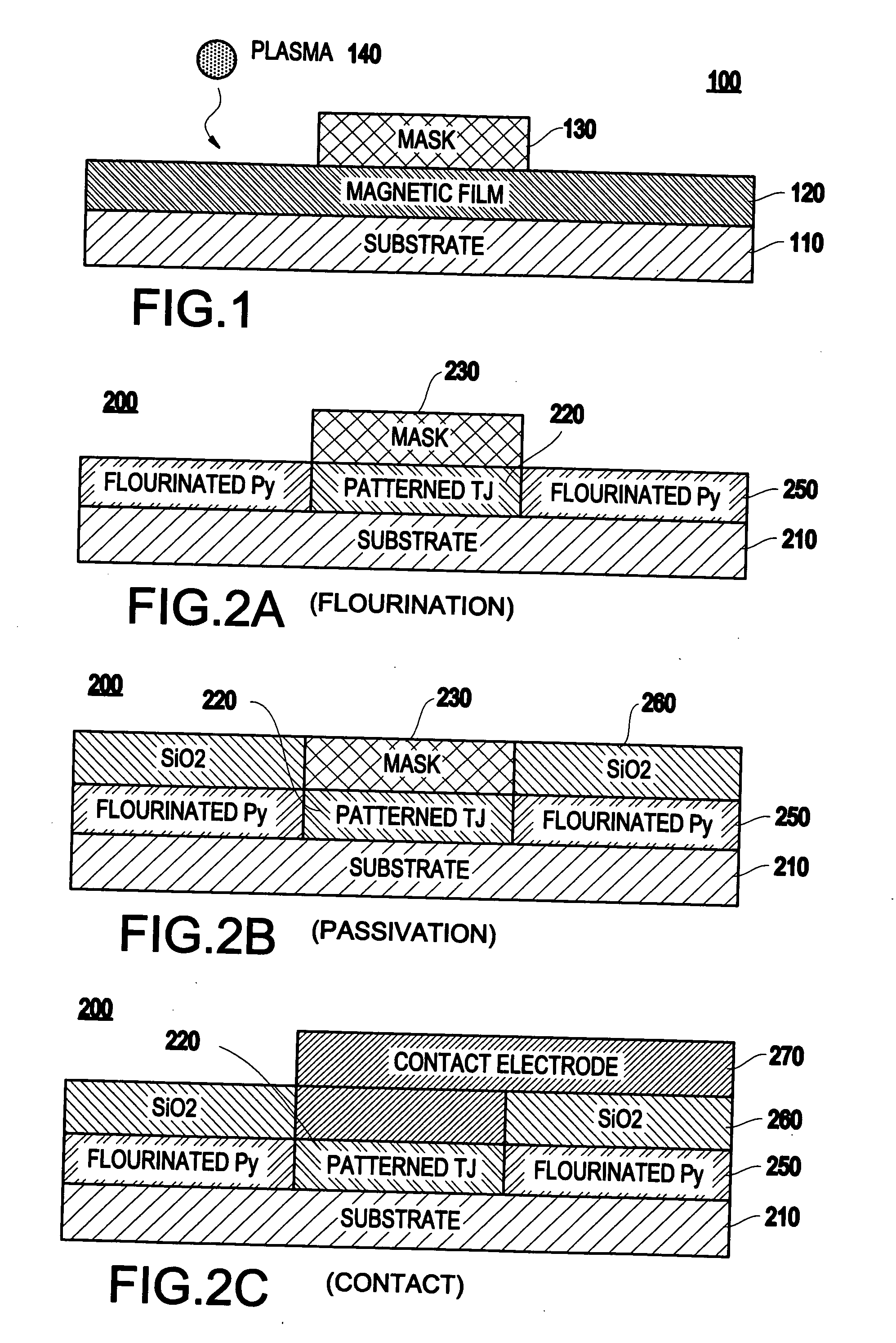
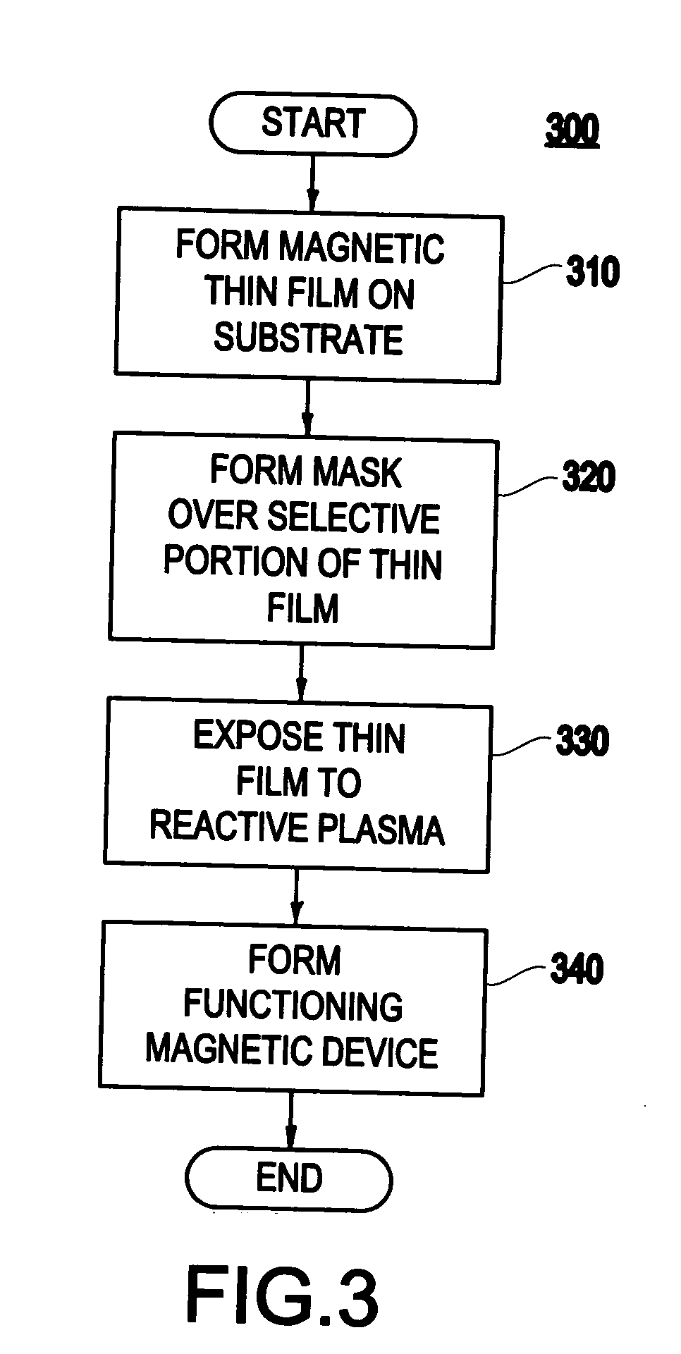
[0026] Referring now to the drawings, and more particularly to FIGS. 1-4B, there are shown preferred embodiments of the method and structures according to the present invention.

[0027] Exemplary Embodiment

[0028] Turning now to FIG. 1 and an exemplary method (and structure formed by the method) of the invention will be described. Specifically, a method of patterning magnetic thin films (e.g., in the exemplary embodiment, a Permalloy™ thin film) which uses chemical transformation of the undesirable part of the film to transform it to be non-magnetic, will be described.

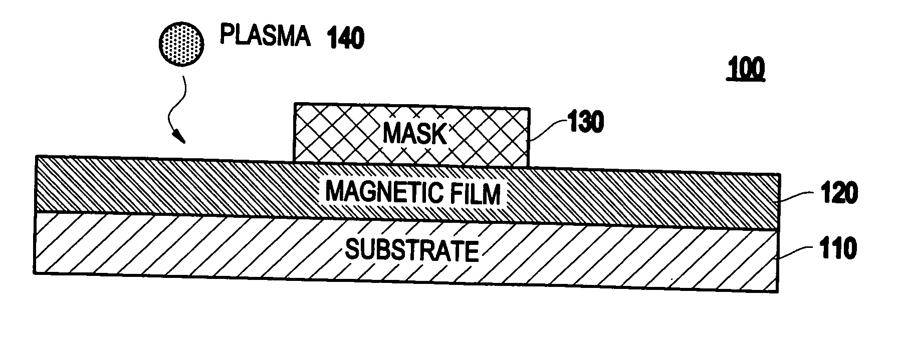
[0029]FIG. 1 illustrates a structure 100 in which a substrate 110 is provided. The substrate may be any suitable material (e.g., silicon, SiO2, sapphire, etc.).

[0030] On a surface (e.g., the top surface) of the substrate 110, a magnetic film 120 (e.g., Permalloy™, alloys of nickel, iron, and cobalt, and any of a number of other magnetic alloy materials) is formed. Preferably, the thin film 120 has a thickness in a ran...


PUM

PropertyMeasurementUnit
Magnetic fieldaaaaaaaaaa
Temperatureaaaaaaaaaa

Abstract

A method (and resulting structure) of patterning a magnetic thin film, includes using a chemical transformation of a portion of the magnetic thin film to transform the portion to be non-magnetic and electrically insulating.

Description

U.S. GOVERNMENT RIGHTS IN THE INVENTION [0001] The subject matter of the present Application was at least partially funded under Contract No. MDA972-99-C-0009 from the U.S. Defense Advanced Research Projects Agency (DARPA).BACKGROUND OF THE INVENTION [0002] 1. Field of the Invention [0003] The present invention generally relates to a method and system for patterning of thin films, and more particularly to a method and system for patterning magnetic thin films using gaseous transformation. [0004] 2. Description of the Related Art [0005] Patterning of thin magnetic films for application in various sensors and devices, such as thin-film disk drive read heads and magnetic memory elements, has relied on removal (e.g., physical removal) of material by reactive ion etching (RIE), ion milling and other subtractive techniques. [0006] Hence, these methods use physical removal of material in order to delineate a region both magnetically and electrically. Typically, the region to be patterned i...

Claims


Application Information

Patent Timeline
IPC IPC(8): C23F4/00H01L21/314G11B5/31G11B5/39H01F10/32H01F41/34H01L21/8246H01L27/105H01L43/08H01L43/12
CPCB82Y10/00B82Y25/00C23F4/00G11B5/3116G11B5/3163Y10T428/12542G11B5/3909H01F10/3254H01F41/308H01F41/34H01L43/12G11B5/3903H10N50/01
Inventor ABRAHAM, DAVID WILLIAMO'SULLIVAN, EUGENE JOHN
Owner IBM CORP
Why Eureka
Try Eureka