Electronic transformer/inductor devices and methods for making same

a technology of electric transformers and transformers, applied in the field of inductive components, can solve the problems of windings not being insulated by electric wires, and achieve the effects of improving magnetic performance, simplifying electrical connections, and superior heat removal

Inactive Publication Date: 2005-05-05
HARDING PHILIP A
View PDF44 Cites 33 Cited by
  • Summary
  • Abstract
  • Description
  • Claims
  • Application Information

AI Technical Summary

Benefits of technology

[0009] In addition to the advantages described above, the preferred embodiments have a number of additional significant advantages. These include: superior heat removal, outside connections that are more accessible to simplify...

Problems solved by technology

Thus, the windings are ...

Method used


Image

  • Electronic transformer/inductor devices and methods for making same
  • Electronic transformer/inductor devices and methods for making same
  • Electronic transformer/inductor devices and methods for making same

Examples


Embodiment Construction

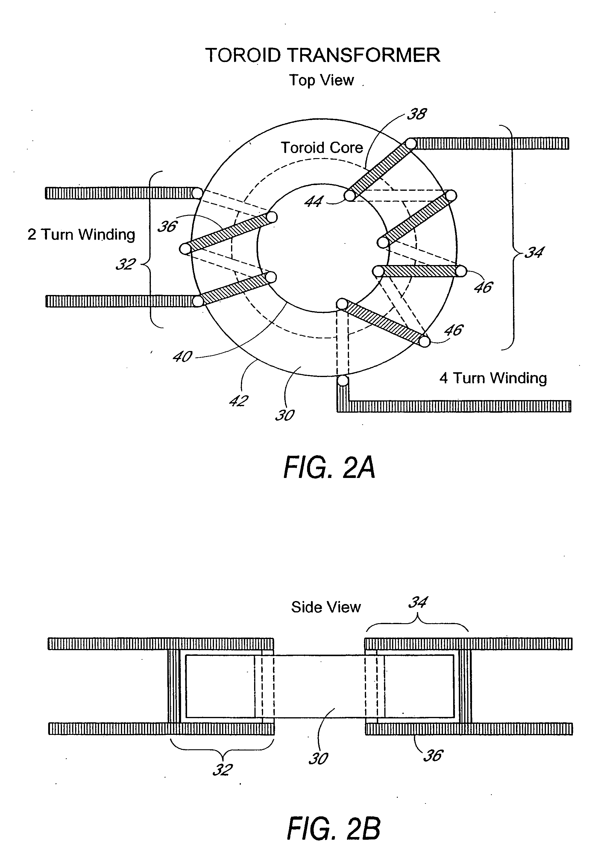
[0035]FIG. 2 illustrates a typical prior art transformer with a toroidal core 30. For simplicity this transformer has two windings of insulated wire: a two-turn winding 32 and a four-turn 34 winding. Each turn 36 encircles the material of the core 30 such that when electrical current is passed through one winding an encircling magnetic flux path 38 flows within the core 30. FIG. 2A illustrates the windings 32, 34 passing through the center of the core 30, and around the outside of the core 30.

[0036] Preferred embodiments of the present invention have a very different core and winding arrangement. In one of these preferred embodiments shown generally in FIG. 3, slab 50 of ferromagnetic material has a top surface 52 and bottom surface 54, and, shown in cross-sections, two outer holes (vias) 56 and one inner hole (via) 64 within the slab 50. As described below, for miniature inductors and transformers, the slab 50 is advantageously a thin layer of ferrite having a relatively high resi...


PUM

PropertyMeasurementUnit
Thicknessaaaaaaaaaa
Electrical conductivityaaaaaaaaaa
Sizeaaaaaaaaaa

Abstract

The present invention relates to the methods of construction for inductive components of, preferably, ferromagnetic materials such as inductors, chokes, and transformers when used as an integral part of the fabrication of PCB's or FLEX's. In one preferred embodiment, holes are formed through a ferromagnetic substrate and plated with conductive material. The arrangement of these holes, and the subsequent design that ensues, will form the inductive components within the plane of the media in which the device is formed; using the substrate for a magnetic core. By using this approach, the inductive components can be miniaturized to physical sizes compatible with the requirements of modem surface mount technology (SMT) for integrated circuitry (IC). This process also allows these components to be fabricated using mass production techniques, thereby avoiding the need to handle discrete devices during the manufacturing process. In another preferred embodiment, a series of thin, concentric high permeability rings are etched on a substrate to provide high permeability transformers and inductors having minimal eddy current effects.

Description

PRIORITY CLAIM [0001] This application claims the benefit of U.S. Provisional Application No. 60 / 234,636 filed Sept. 22, 2000 entitled “Electronic Transformer / Inductor Devices And Methods For Making Same” and U.S. Provisional Application No. 60 / 237,356 filed Sept. 27, 2000 entitled “Electronic Transformer / Inductor Devices And Methods For Making Same.”FIELD OF THE INVENTION [0002] The present invention relates to inductive components and methods for manufacturing these components. BACKGROUND OF THE INVENTION [0003] Inductive components are commonly fabricated using ferromagnetic cores and windings of insulated electrical wire. The ferromagnetic cores are typically toroidal cores, rod cores, or assemblies made of a lower E shaped ferromagnetic part and a ferromagnetic cap connecting the three legs of the E such as shown in FIG. 1. [0004] The toroid and rod cores are manually or automatically wound with the insulated copper wire to form a number of multiple turn windings for a transfor...

Claims


Application Information

Patent Timeline
IPC IPC(8): H01F17/00H01F41/00H01F17/04H01F30/00H01F37/00H01F41/04H05K1/16H05K3/06H05K3/42H05K3/46
CPCH01F17/0033Y10T29/49073H05K1/165H05K3/06H05K3/429H05K3/4611H05K2201/086H05K2201/09063H05K2201/097H05K2201/10416Y10S29/016Y10T29/49165Y10T29/49075Y10T29/4902H01F41/046
Inventor HARDING, PHILIP A.
Owner HARDING PHILIP A
Why Eureka
Try Eureka