
Shielded cable, and bioelectrical impedance value or biological composition data acquiring apparatus using the same

a bioelectrical impedance value and cable technology, applied in the direction of insulated conductors, power cables, cables, etc., can solve the problems of large errors, poor measurement reproducibility, and prone to measurement errors of core cables, so as to reduce electromagnetic wave noise, suppress the increase in the cost of the apparatus, and improve the resistance to electromagnetic wave noise coming in from the outside

Active Publication Date: 2005-05-12
TANITA CORP
View PDF16 Cites 32 Cited by
  • Summary
  • Abstract
  • Description
  • Claims
  • Application Information

AI Technical Summary

Benefits of technology

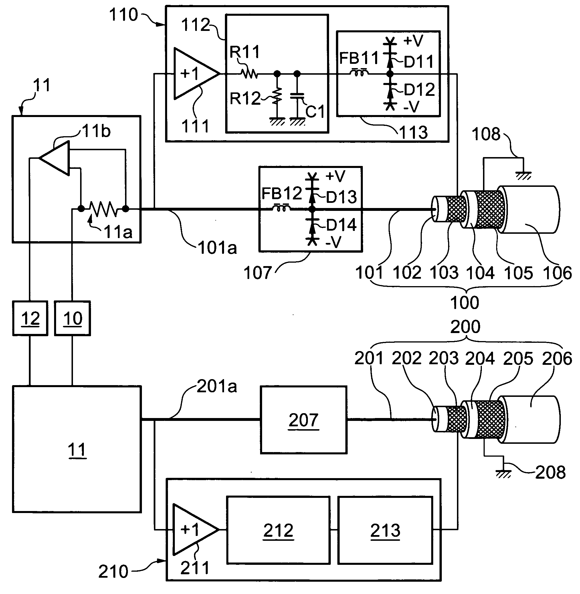
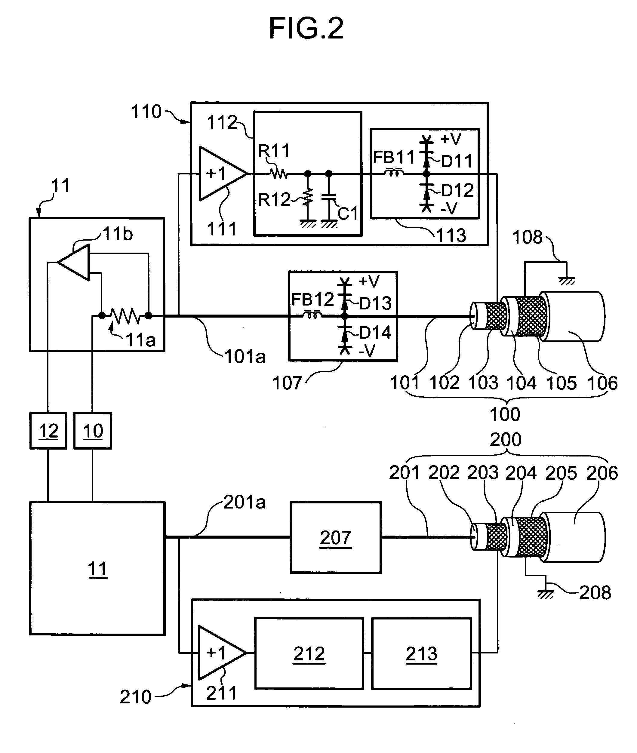
[0024] In a shielded cable according to the present invention, an output voltage from a drive circuit can be decreased in a predetermined frequency band not required for measurements by adjusting (arbitrarily setting) the frequency characteristic of a band limiting circuit incorporated in the drive circuit situated between a core wire and a shield. As a result, while the effect of an active shield is retained in a frequency band (including a band required for the measurements) excluding the predetermined frequency band, the effect of the active shield can be decreased in the predetermined frequency band, i.e., the gain of a buffer amplifier constituting the drive circuit can be made smaller than 1 deliberately. Accordingly, the buffer amplifier may be any buffer amplifier which accommodates to a frequency band (including the band required for the measurements) excluding the predetermined frequency band, and it becomes possible to form a low-cost active shield by use of an inexpensive buffer amplifier. At the same time, an effect of decreasing electromagnetic wave noise irradiated to the outside through the shield can be expected.
[0025] Further, when a second shield connected to a stable potential with a low impedance, preferably a ground potential, is provided around the circumference of the shield, the electromagnetic wave noise irradiated to the outside through the shield can be suppressed nearly securely, and resistance to electromagnetic wave noise coming in from the outside can be improved. Further, even when the second shield is provided, the second shield does not influence an electrical signal passing through the core wire because the active shield functions effectively in the frequency band required for the measurements.
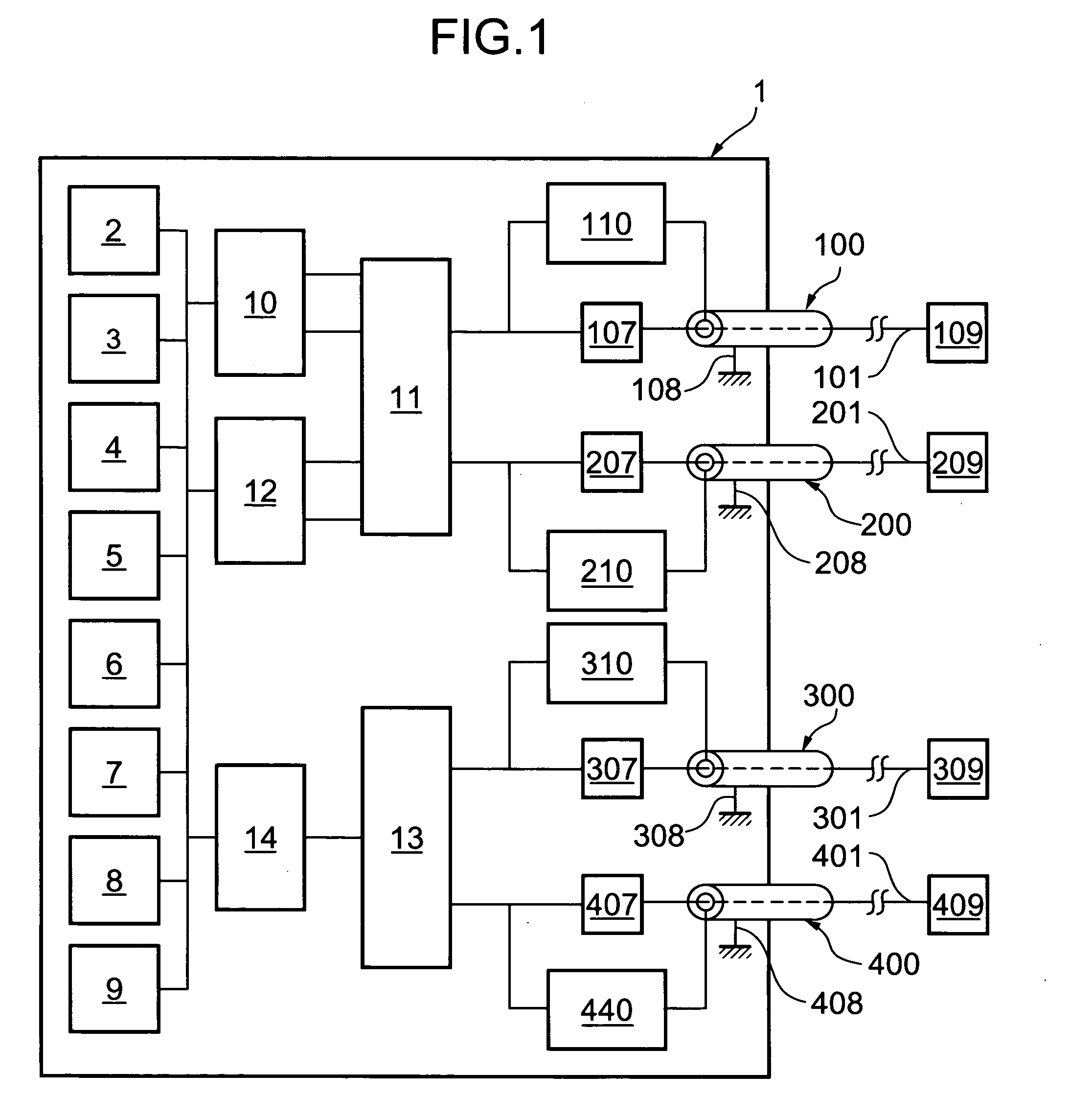
[0026] Further, in an apparatus for acquiring a bioelectrical impedance or biological composition data according to the present invention, the shielded cable according to the present invention is used as electric cables which connect electrodes to the main unit of the apparatus. Thus, while the occurrence of measurement errors is inhibited by maintaining the effect of the active shield in a frequency band required for measurement(s) of high frequency current value supplied to a living body and / or a potential difference occurring in the living body, an increase in the cost of the apparatus can be suppressed as a whole by suppressing the cost of a drive shield for the active shield.
[0027] Further, when the electric cable has the second shield connected to a stable potential with a low impedance, preferably a ground potential of the main unit of the apparatus, irradiation of electromagnetic wave noise generated inside the main unit of the apparatus to the outside and penetration of electromagnetic wave noise from the outside into the main unit of the apparatus can be prevented. Thus, even in the presence of other electronic devices, the present apparatus can be used without influencing these other electronic devices or being influenced by these other electronic devices.

Problems solved by technology

However, the single core cable is liable to cause measurement errors since electrical signals passing through the core wire also pass through another cable through an electrostatic capacitance between the cables or dissipate into the ground through a stray capacitance between the cable and the ground.
The degrees of these errors change because the electrostatic capacitance between the cables or the stray capacitance between the cable and the ground change according to the positions of the cables, thereby causing significantly poor measurement reproducibility.
Further, these errors become large when relatively long cables are used (when the distance between the main unit of the apparatus and a living body to be measured is large) and become larger along with an increase in the frequency of an electrical signal used for measurements.
In particular, an electric cable for measuring a potential difference which carries the potential signal of a living body has a very high impedance and is vulnerable to noise from the outside and susceptible to the influence of the noise.
The influence causes errors in the absolute value of a bioelectrical impedance and the phase thereof.
The latter (error in the phase) is liable to become larger along with an increase in the frequency of an electrical signal used for measurements.
The foregoing active shield has a problem that a drive circuit therefor requires a buffer amplifier which operates stably over a wide frequency band so as to obtain the effect of suppressing the measurement errors by the active shield stably, thereby making the cost of the apparatus high.
In general, a buffer amplifier with a capacitive load connected thereto is liable to cause high frequency parasitic oscillation and is often unstable.
When such a buffer amplifier with a gain of +1 is to be achieved over a wide frequency band, the cost of the buffer amplifier increases, thereby making the cost of the whole apparatus high.
This further increases the cost of the amplifier.
Further, the active shield has a possibility that the shield itself acts as an antenna and irradiates therethrough electromagnetic wave noise generated inside the main unit of an apparatus to which the shield is connected to the outside.
However, when the high input impedance buffer circuit is not provided in the vicinity of electrodes, an electrical signal passing through the core wire is more liable to dissipate into the ground via the shield connected to the ground potential along with an increase in the frequency of the electrical signal, thereby causing measurement errors.

Method used


Image

  • Shielded cable, and bioelectrical impedance value or biological composition data acquiring apparatus using the same
  • Shielded cable, and bioelectrical impedance value or biological composition data acquiring apparatus using the same
  • Shielded cable, and bioelectrical impedance value or biological composition data acquiring apparatus using the same

Examples


example

[0036] Hereinafter, a suitable embodiment of the present invention will be described with reference to the drawings. FIG. 1 is a schematic diagram showing the overall constitution of a biological composition data acquiring apparatus according to the present invention. FIGS. 2 and 3 are schematic diagrams showing the structures of the principal parts of shielded cables according to the present invention which are adopted in the biological composition data acquiring apparatus of FIG. 1. FIG. 4 is a diagram showing the frequency characteristic of a drive circuit of the shielded cable according to the present invention. FIG. 5 is a diagram showing the constitution patterns of the drive circuit of the shielded cable according to the present invention.

[0037] The biological composition data acquiring apparatus according to the present invention supplies a high frequency weak or small current between any two points of a subject (living body) so as to measure a potential difference occurrin...


PUM


Abstract

There are provided a shielded cable comprising a core wire for carrying an electrical signal, and a shield provided around the circumference of the core wire and connected to the core wire via a drive circuit, wherein the drive circuit has a band limiting circuit which decreases an output voltage in a predetermined frequency band; and an apparatus which acquires a bioelectrical impedance value or biological composition data by using the shield cable.

Description

BACKGROUND OF THE INVENTION [0001] (i) Field of the Invention [0002] This invention relates to a shielded cable used to carry an electrical signal and to an apparatus which acquires a bioelectrical impedance value or biological composition data by using the shielded cable. [0003] (ii) Description of the Related Art [0004] An apparatus which acquires a bioelectrical impedance value by supplying a high frequency weak or small current between any two points of a living body through electrodes and measuring a potential difference in this current path through electrodes or an apparatus which acquires biological composition data based on the bioelectrical impedance value or the measured potential difference is well known. The apparatus may use a plurality of electrodes connected to the main unit of the apparatus via electric cables so as to supply a high frequency current between any two points of a living body and / or measure a potential difference in this current path. [0005] As the elec...

Claims


Application Information

Patent Timeline
IPC IPC(8): A61B5/05A61B5/04H01B11/06H01B11/20
CPCH01B11/206
Inventor FUKUDA, YOSHINORI
Owner TANITA CORP
Learn More