Battery power circuit

a power circuit and battery technology, applied in the direction of engine starters, electric generator control, instruments, etc., can solve the problems of inability to supply a sufficient electric power to a motor, inability to obtain sufficient motor output, and inability to start-up operation of the motor of a vehicle. to prevent the reduction of electric power, increase the charge of electric power

Inactive Publication Date: 2005-05-12
MITSUBISHI ELECTRIC CORP
View PDF6 Cites 61 Cited by
  • Summary
  • Abstract
  • Description
  • Claims
  • Application Information

AI Technical Summary

Benefits of technology

[0008] The present invention is made to solve the above-mentioned problems, and it is an object of the present invention to provide a power circuit for a battery which is capable of, even when an idle-stop operation is continuously performed, preventing reduction of an electric power supplied to a motor at start-up to obtain a predetermined engine rpm.
[0009] In addition, it is a second object of the present invention to obtain a power circuit for a battery which is capable of regenerating an instantaneous large energy generated by an electric motor during, for example, breaking on a vehicle, without damaging a battery.
[0011] The control means of the present invention detects a voltage of the energy storage source that is disposed on a high voltage side, from among the first and second energy storage sources of the series-connected power supply. When the detected voltage is lower than a predetermined first threshold voltage, the energy storage source disposed on the high voltage side is charged with electricity by the DC / DC converter. Thus, even when the idle-stop operation is continuously carried out, it is possible to prevent reduction of the electric power supplied to the motor at start-up, and hence it is possible to obtain the predetermined engine rpm.
[0012] In addition, the power circuit for a battery of the present invention further includes an electric power conversion circuit for shifting an electric power between an electric motor connected to an axle of a vehicle, and the first and second energy storage sources connected in series with each other. When the first and second energy storage sources are charged with the regenerative electric power of the electric motor through the electric power conversion circuit, the control means controls the DC / DC converter so that an input current to the first energy storage source becomes equal to or smaller than an allowable input current of the first energy storage source. Hence, it is possible to increase a charge electric power for a battery and a capacitor.

Problems solved by technology

In the conventional power circuit for a battery, there is a problem in that if an idle-stop operation (stop / start-up operation) is continuously carried out, then the recharging for a capacitor group connected in series with a battery group becomes insufficient so that it becomes impossible to supply a sufficient electric power to a motor through an inverter, and hence a predetermined start-up operation by the motor of a vehicle can not be carried out.
In addition, there arises a problem in that a sufficient motor output can not be obtained due to insufficiency in voltage of the capacitor, and hence the start-up by the motor can not be carried out.
In addition, if the idle-stop operation is continuously carried out, then a sufficient period of time cannot be secured to recharge the capacitor with electricity.
Then, there arises a problem in that if the DC / DC converter is operated with a fixed output independently of the capacitor voltage, then the efficiency of the overall battery drive circuit system including a battery, a capacitor, and a DC / DC converter deteriorates depending on the capacitor voltage values.
The deterioration of the efficiency causes an increase in a quantity of calorification of the overall system.
In particular, there is a concern about reduced life of the capacitor due to rise in temperature caused by the calorification, and the heating of other apparatuses.
In addition, due to internal resistances that exist in the capacitor and the battery, there is a possibility that in outputting a large electric power at the engine restart-up or the like, a voltage drop due to the internal resistance exerts adverse influences on other on-vehicle apparatuses.
In particular, when a charge voltage of the capacitor is low or a state of charge (SOC) of the battery is low, there is a problem in that a battery current required for restart-up of an engine is increased to decrease a battery output voltage.
Thus, the high speed charging characteristics of the capacitor can not be utilized, and hence it is necessary to limit the regenerated output of the electric motor.

Method used


Image

  • Battery power circuit
  • Battery power circuit
  • Battery power circuit

Examples


embodiment 1

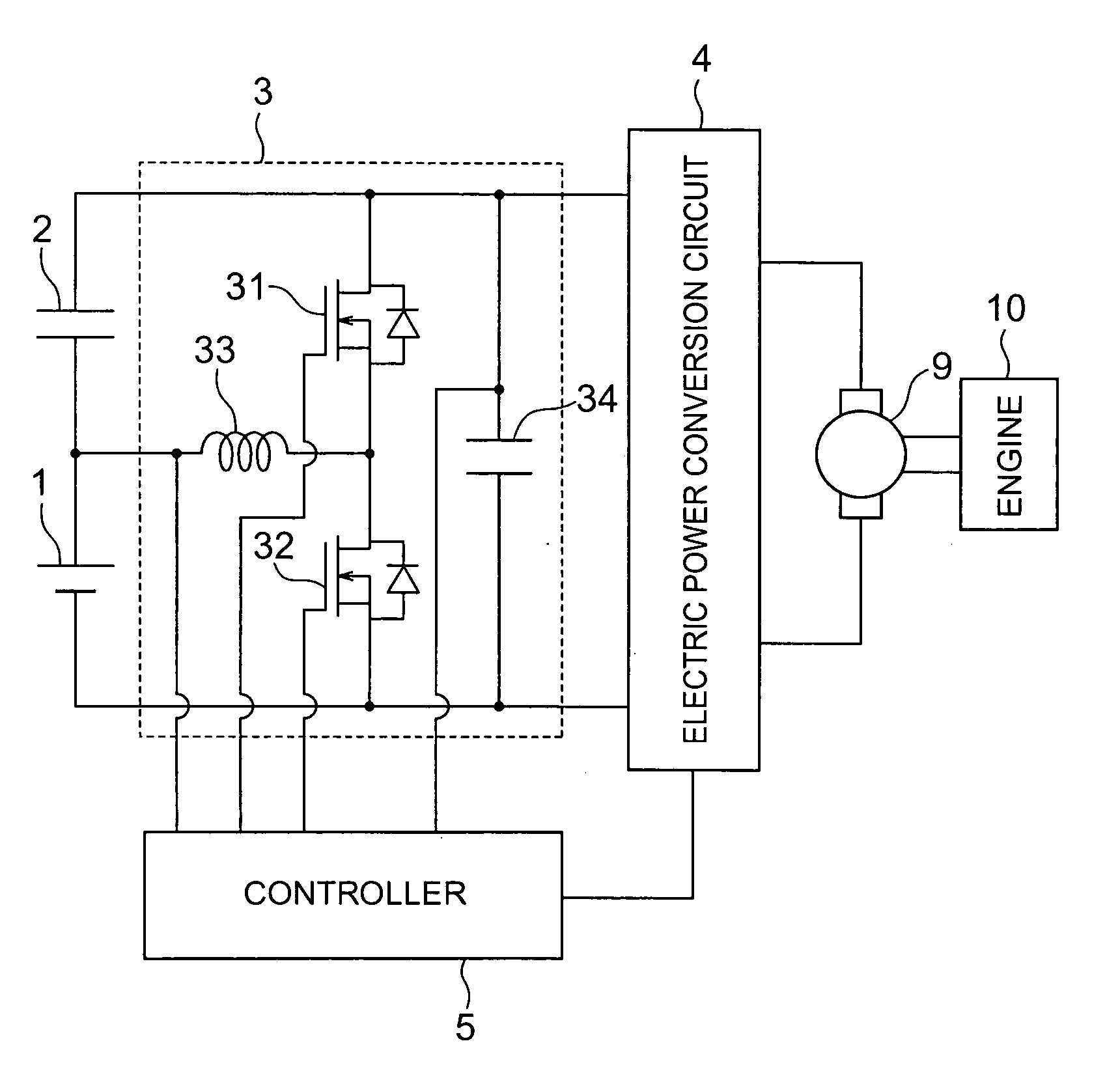
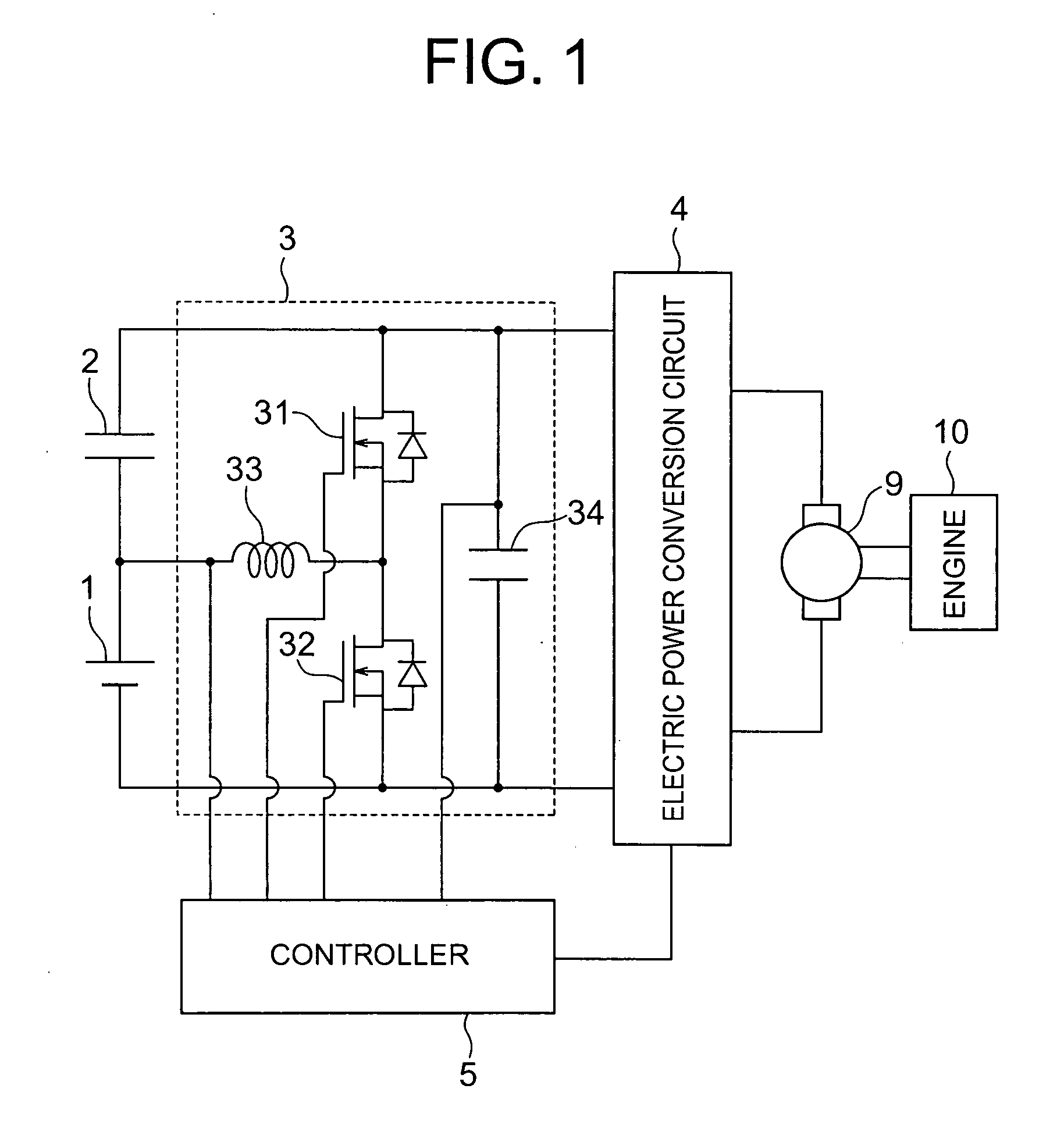
[0037]FIG. 1 is a circuit diagram showing a configuration of a power circuit for a battery according to Embodiment 1 of the present invention. As shown in the figure, a battery (first battery group) 1 and a capacitor group 2 as a second battery group are connected in series with each other to constitute a series-connected power supply. The capacitor group is constituted by capacitors each having a large capacity. For example, an electrical double layer capacitor, an aluminum electrolytic capacitor or the like can be used in the capacitor group. While not illustrated in FIG. 1, an electrical load (not shown; refer to Patent Document 1) such as an on-vehicle apparatus is connected to the battery 1. Here, in the following description, it is supposed that the battery 1 is an energy storage source, disposed on a low voltage side, of the above-mentioned series-connected power supply, and the capacitor group 2 is an energy storage source, disposed on a high voltage side, of the above-menti...

embodiment 2

[0062]FIG. 9 is a flow chart showing a flow of an operation of a power circuit for a battery according to Embodiment 2 of the present invention. Note that since a configuration of the power circuit for a battery according to Embodiment 2 of the present invention is the same as that of Embodiment 1 shown in FIG. 1, the reference should be made to FIG. 1 in this regard, and a detailed description is omitted here.

[0063] As shown in FIG. 9, in Embodiment 2, first of all, when an engine start-up command is issued in Step S10, in Step S11, it is judged whether or not the voltage across the terminals of the battery 1 is higher than a second threshold voltage VTH2 (e.g., 8.0 V). If it is judged in Step S11 that the voltage across the terminals of the battery 1 is higher than the second threshold voltage VTH2, then the operation proceeds to Step S12. The maximum efficiency control described in Embodiment 1 is carried out, and in Step S15, the engine is started. At this time, a judgment on t...

embodiment 3

[0084]FIG. 11 is a circuit diagram showing a configuration of a power circuit for a battery according to Embodiment 3 of the present invention. FIG. 12 is a detailed block diagram of a controller shown in FIG. 11. FIGS. 13 and 14 are a flow chart of regenerative control in FIG. 11. FIG. 15 is a diagram showing how charging is carried out in a power circuit for a battery shown in FIG. 11.

[0085] As shown in FIG. 11, the power circuit for a battery includes: a battery 1 as a first energy storage source; a capacitor 2 which is connected in series with the battery 1 and which serves as a second energy storage source having an allowable input current larger than that of the battery 1; a DC / DC converter 3 inserted between the battery 1 and the capacitor 2; an electric power conversion circuit 4 connected between terminals of a series-connected body of the battery 1 and the capacitor 2; and a controller 5 for controlling the DC / DC converter 3 and the electric power conversion circuit 4.

[0...


PUM


Abstract

A power circuit for a battery for, even when an idle-stop operation is continuously performed, preventing reduction of an electric power supplied to a motor at start-up to obtain a set engine rpm. The power circuit includes a series-connected power supply in which a battery having a load and a capacitor group are connected in series with each other, a DC / DC converter for shifting electric power between the battery and the capacitor group, and between the battery and the load, and a controller for controlling the DC / DC converter. The controller detects the voltage of the capacitor group, and when the voltage detected is lower than a first threshold voltage, controls the DC / DC converter so that the capacitor group is charged with electricity.

Description

TECHNICAL FIELD [0001] The present invention relates to a power circuit for a battery, and more particularly to a power circuit for a battery which is installed in a vehicle such as an automobile to be used therein. BACKGROUND ART [0002] In a conventional power circuit for a battery, in order to reduce a capacity of a capacitor while ensuring an output electric power in start-up and power-running of an electric motor, a capacitor (or a high output battery having a small capacity) is connected in series with a battery of 12 V, and a DC / DC converter having a small capacity is added for the purpose of shifting an electric energy between the capacitor and the battery. In this power circuit for a battery, the DC / DC converter is operated for boosting in power running of the electric motor, whereby a desired output can be obtained with the capacitor having a relatively small capacity (or a battery having a relatively small capacity) (refer to JP 2002-218667 A (FIG. 3) for example). [0003] ...

Claims


Application Information

Patent Timeline
Patent Type & Authority Applications(United States)
IPC IPC(8): F02N11/08H02M3/155H02J7/02H02J7/14H02P9/04
CPCF02N11/0866F02N2011/0885Y02T10/7022H02J7/1438Y02T10/7016F02N2011/0888F02N2300/106F02N2250/02F02N2200/063Y02T10/70
Inventor OKUDA, TATSUYAURAKABE, TAKAHIRO
Owner MITSUBISHI ELECTRIC CORP
Why Eureka
Try Eureka