Electrochromic device based on nanocrystalline materials

a nano-crystalline material and electrochromophore technology, applied in semiconductor devices, instruments, optics, etc., can solve the problems of inability to classify the electrochromophore as n, poor long-term stability, spontaneous bleaching, etc., to improve stability, improve memory effect, and rapid colour change

Inactive Publication Date: 2005-05-19
NTERA LTD (IE)
View PDF5 Cites 22 Cited by
  • Summary
  • Abstract
  • Description
  • Claims
  • Application Information

AI Technical Summary

Benefits of technology

[0014] An object of the present invention is to provide an electrochromic device which, compared to prior art, exhibits rapid colour change, has a good memory effect, has improved stability, exhibits black colouration and which may be prepared using low cost processes.

Problems solved by technology

Firstly, there are devices based on ion insertion reactions at essentially dense metal oxide electrodes.
However, since the surface area in contact with the electrolyte is not significantly larger than the geometric area of the electrode, the use of metal oxide electrodes requires bulk intercalation of ions.
Secondly, there are solution-phase electrochromic devices, in which one or two electrochromic compounds are dissolved in an electrolyte between two electrodes.
Systems of this type are not bistable and therefore bleach spontaneously when the current is off.
Thirdly, there are devices based on a transparent conducting substrate coated with a polymer to which a redox chromophore is bound.
In such cases it is not possible to classify the electrochromophore as n-type or p-type.
Long-term stability appears to be poor as prolonged cycling leads to metal particle and dendrite formation.
It is also known that such electrochromic devices exhibit problems with bubble formation.
The unstable metal surface is further not a good substrate for additional films, e.g. a white reflector.
Metal ions may also be deposited in the coloring electrode or in other locations in the display, causing unwanted irreversible blackening.
However, Enright et al mentions that, despite the rapid switching times in such films, the associated change in transmittance is not sufficient for a commercial device.
Naked electrodes, that is electrodes which does not have an redox active species added to the surface, have not been considered in previous displays with electrochromic capacitive electrodes, neither as non-colouring counter electrodes nor as counter electrodes, since naked electrodes has been considered to have too low charge capacity and colouration efficiency to be used in displays.

Method used


Image

  • Electrochromic device based on nanocrystalline materials
  • Electrochromic device based on nanocrystalline materials

Examples


specific example

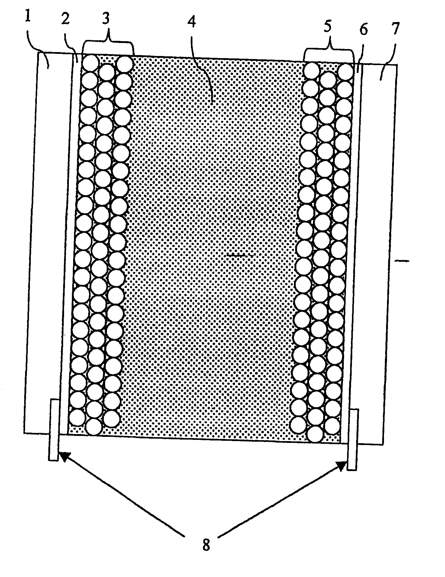
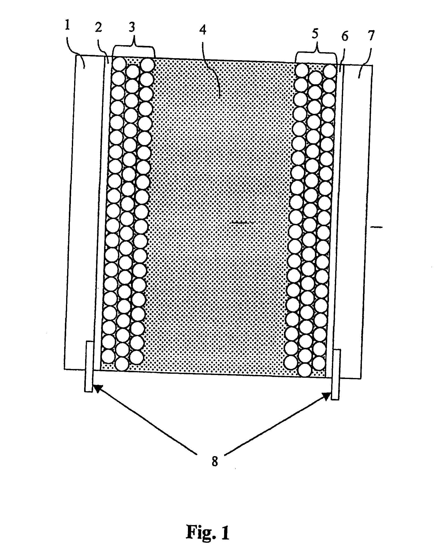
[0047] An electrochromic display according to the invention may be provided as described in detail below.

[0048] Bis-(2-phosphonoethyl)-4,4′-bipyridinium dichloride is adsorbed to the surface of a 4 m thick nanostructured film of TiO2 on a conducting glass plate (0.5 μm fluorine-doped SnO2 on 2 mm glass). This electrode is transparent, but colours blue upon reduction. A nanostructured carbon film (10-50 μm thick), comprising carbon black and graphite particles, is deposited on a second conducting plate. On top of this film a porous white light-scattering film is deposited as a reflector. The two plates are assembled face-to-face using a hot-melting plastic at the uncovered edges of the two plates. Electrolyte (0.2 M tetrabutylammonium trifluoromethanesulfonate in 3-methoxypropionitrile) is introduced in the space between the two electrodes. The resulting electrochromic display has a good memory effect and stability (>100,000 cycles without severe degradation).

[0049] Above a number ...


PUM

PropertyMeasurementUnit
particle sizeaaaaaaaaaa
porosityaaaaaaaaaa
thicknessaaaaaaaaaa

Abstract

An electrochromic device, comprising a first electrode (3), a second electrode (5) and an electrolyte (4) separating the electrodes (3, 5), where at least one of said first and second electrodes includes an electrically active structure which have an at least dual state visual appearance depending on the potential difference between the first and the second electrode.

Description

TECHNICAL FIELD OF THE INVENTION [0001] The present invention relates to an electrochromic device and a method for change of state of an electrically active structure in an electrochromic device. The invention relates more specifically to an electrochromic device comprising at least one nanostructured electrode which does not have an redox active species added to the surface. TECHNICAL BACKGROUND [0002] Available electrochromic devices may be divided into at least four classes: [0003] Firstly, there are devices based on ion insertion reactions at essentially dense metal oxide electrodes. To ensure the desired change in transmittance needed to bring about a color change, a certain number of ions must be intercalated into the electrode to compensate for the accumulated charge. However, since the surface area in contact with the electrolyte is not significantly larger than the geometric area of the electrode, the use of metal oxide electrodes requires bulk intercalation of ions. As a c...

Claims


Application Information

Patent Timeline
Patent Type & Authority Applications(United States)
IPC IPC(8): B82Y20/00G02F1/1523G02F1/1524G02F1/155
CPCB82Y20/00G02F1/15G02F1/1523G02F2202/36G02F2001/1504G02F2001/1555G02F1/155G02F2001/15025G02F1/1524
Inventor EDWARDS, MARTENHAGFELDT, ANDERSBOSCHLOO, GERRITLINDQVIST, STEN-ERIK
Owner NTERA LTD (IE)
Why Eureka
Try Eureka