
Microtransformer for system-on-chip power supply

Inactive Publication Date: 2005-05-19
MICRON TECH INC
View PDF10 Cites 32 Cited by
  • Summary
  • Abstract
  • Description
  • Claims
  • Application Information

AI Technical Summary

Benefits of technology

[0013] The present invention provides an integrated circuit microtransformer capable of operating at high frequencies with high efficiency, low losses, and high magnetic permeability.
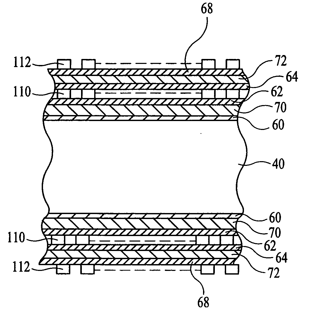
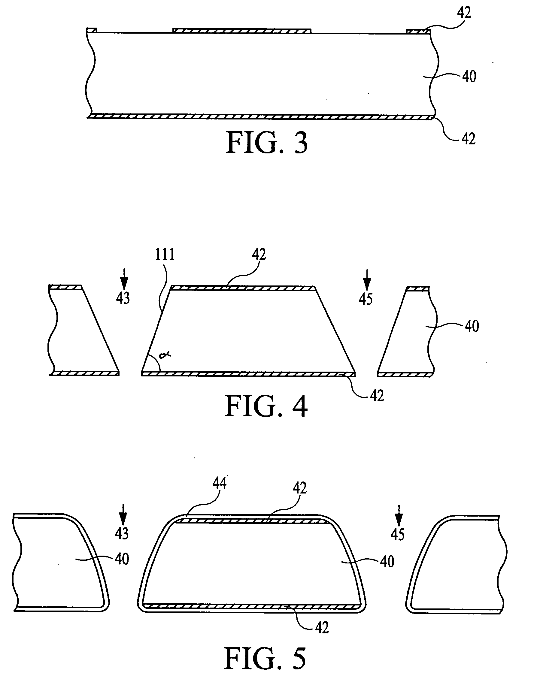
[0014] The microtransformer of the present invention uses a silicon substrate with a pair of through-holes on which an insulating silicon oxide layer is first deposited on all surfaces of the substrate. A magnetic film, such as Permalloy or others, is further deposited on the silicon oxide layer followed by the application of another insulating layer. Coils are fabricated next by patterned deposition on both sides of the substrate and through the holes. The pair of through-holes allows the winding of a single coil or the winding of primary and secondary coils to pass through the holes and thus to reside on both surfaces of the substrate. The typical through-hole size is approximately 1 mm, which can accommodate, for example, up to 83 windings of 8 μm lines on a 12 μm spacing. The coils can be, for example, single coils, or primary or secondary coils of a transformer structure, with secondary coils having one or more output taps to supply different output voltages. For better flux closure, various magnetic layers and insulators can be deposited on top of the windings. The primary and secondary windings of a transformer can also be wound through the holes, but at different levels.

Problems solved by technology

Power consumption remains, however, a critical issue, especially for portable devices having complex circuitry, which requires an always increasing number of devices to be integrated on one chip.
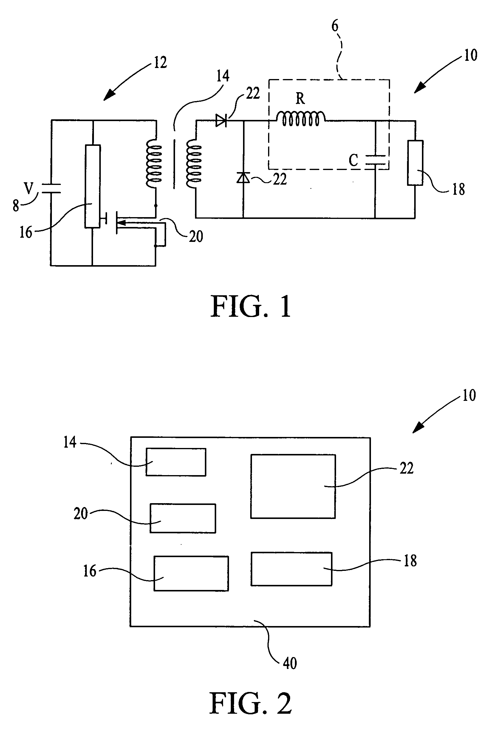
Since a typical DC-DC converter consists of semiconductor devices, resistors, capacitors, and electromagnetic components, such as transformers and inductors, among others, a key issue for the system-on-chip DC-DC converter is integrating both semiconductor and electromagnetic devices into a chip, while reducing the size of the electromagnetic components, which tend to occupy a large amount of space.
The implementation of a truly high performance system-on-chip DC-DC converter with electromagnetic elements poses various problems, mainly because of the growing demand for increased efficiency at high frequency operations.
Yet, at frequencies higher than 1 MHz, operating frequency increases tend to have a detrimental effect on the efficiency of the devices.
Multilayered integrated circuit structures for forming electromagnetic components have attempted to address the efficiency issue, but have reached only limited results.
Another disadvantage of electromagnetic devices operating at high frequencies is the limitation posed by the width of the winding conductor.
Consequently, the current capacity of the magnetic induction is also limited and, in turn, limits the current density in the coil.
Further, planar electromagnetic elements fabricated today are not yet small enough to be integrated with other circuit elements, making it practically impossible to manufacture sufficiently small system-on-chip power supplies.

Method used


Image

  • Microtransformer for system-on-chip power supply
  • Microtransformer for system-on-chip power supply
  • Microtransformer for system-on-chip power supply

Examples


Embodiment Construction

[0038] In the following detailed description, reference is made to various exemplary embodiments for carrying out the invention. These embodiments are described with sufficient detail to enable those skilled in the art to practice the invention, and it is to be understood that other embodiments may be employed, and that structural, electrical and process changes may be made, and equivalents substituted, without departing from the invention. Accordingly, the following detailed description is exemplary and the scope of the present invention is defined by the appended claims.

[0039] The term “substrate” used in the following description includes any semiconductor-based structure having an exposed silicon surface in which the structure of this invention may be formed. The term “substrate” is to be understood as including substrates formed of silicon, silicon-on-insulator, doped and undoped semiconductors, epitaxial layers of silicon supported by a base semiconductor foundation, and othe...


PUM


Abstract

A microtransformer for a high-performance system-on-chip power supply is disclosed. Through-wafer openings in a substrate allow the primary and secondary wiring on both surfaces of the silicon substrate. An insulating silicon oxide layer is first deposited on all surfaces of the substrate. A magnetic film is further deposited on the silicon oxide layer followed by the application of another insulating layer. Coils are fabricated next by patterned deposition on both sides of the substrate and through the holes. The coils can be, e.g., single coils or primary or secondary coils of a transformer structure, with secondary having one or more output taps to supply different output voltages. For better flux closure, various magnetic layers and insulators can be deposited on top of the windings.

Description

CROSS-REFERENCE TO RELATED APPLICATION [0001] This application is a continuation-in-part of application Ser. No. ______ (U.S. Pat. No. ______), filed Dec. 10, 1999.FIELD OF THE INVENTION [0002] The present invention relates generally to semiconductor circuits, and in particular to a method for the fabrication of microtransformers which can be used in a system-on-chip power supply. BACKGROUND OF THE INVENTION [0003] The system-on-chip concept refers to a system in which, ideally, all the necessary integrated circuits are fabricated on a single die or substrate. Various packaging schemes have been proposed to achieve integration of chips with different functionalities in a single package by mounting them on a silicon interposer to form a circuit module. For example, the simplest scheme is the chip-on-chip module, in which a microprocessor chip and a memory chip are stacked together, face to face or through a silicon interposer, using micro bump bonding (MBB) technology. [0004] Integra...

Claims


Application Information

Patent Timeline
IPC IPC(8): H01F17/00H01F41/04H01L23/14H01L23/48H01L23/498H01L23/50H01L23/522H01L23/64H01L25/065H02H7/00
CPCH01F17/0033H01F41/046H01L23/147H01L23/481H01L23/49827H01L2924/19103H01L23/5227H01L23/645H01L2224/16145H01L2924/01078H01L2924/01079H01L23/50H01L2224/05571H01L2224/05573H01L2924/00014H01L2224/05599
Inventor AHN, KIE Y.FORBES, LEONARD
Owner MICRON TECH INC
Learn More