System and method for thermal to electric conversion

a technology of thermal to electric conversion and system, applied in can solve the problems of poor energy conversion efficiency, high installation cost, and the field of solar generation suffers, and achieve the effects of low cost, efficient storage, and efficient storag

Inactive Publication Date: 2005-05-26
PRACTICAL TECH
View PDF25 Cites 82 Cited by
  • Summary
  • Abstract
  • Description
  • Claims
  • Application Information

AI Technical Summary

Benefits of technology

[0010] A solar thermal input consists of a solar concentrator focused on an optical absorber material. The maximum attainable temperature is dependent on the amount of concentration, load, and parasitic losses. A parabolic trough concentrator with a circulating thermal transfer fluid collects thermal energy. A heat pump elevates the temperature of the energy and the energy is stored in a thermal mass. Use of a circulating fluid further allows for: a large thermal storage mass, peak insolation to be efficiently stored and converted to electricity at a lower rate, low cost concentrators, for the energy storage to be located in an environmentally protected location, for Uninterruptible Power Supply functionality, and storm damage to only impact the collectors. Thermal storage mass may be sized for seasonal insolation variations. The use of a heat pump allows efficient storage, low cost solar concentrators, and a high temperature output. Highly concentrated insolation from a parabolic dish collector may be used without a heat pump. Combined Cooling Heat and Power may be utilized either as an energy input or output.
[0011] Waste heat may also be used as an input to the heat pump. A multi fuel fossil fueled burner may provide backup. The burner may include a catalytic converter or an afterburner to reduce NOx emissions and a recuperator to improve efficiency. The heat pump and circulating fluid through the trough collectors prevents back streaming losses from the storage.
[0012] The system load may be a thermal load, such as a kiln, or building heating and cooling. Thermal storage reduces the dispatchability limitations with other solar kilns. The system may also include a TPV generator or other generator to supply an electric load. TPV generator consists of a 3D inverse opal photonic band gap (PBG) emitter material including a material with a complex dielectric constant, a high refractive index contrast between materials, and predominantly visible emissions, a filter, an iris to control energy incident on a Photo Voltaic cell, a PV cell, an ultracapacitor, and an output power supply. The iris matches the maximum power point of the PV to the load. An impulse is applied to the iris or to the electric load to determine the maximum power point. The ultracapacitor provides transient energy for a load step, switch mode power supply as a load, motor start, or maximum power point tuning impulse. The system benefits over PV plus STPV systems in that only one set of PV cells are required.
[0013] Vacuum and reflective insulation increase system efficiency. Multiple systems can be connected for larger output or for increased reliability. Three or more output busses can be connected to multiple generators, with proper fusing, for even higher reliability systems. Other features may include support for load management, grid connection, or remote maintenance.

Problems solved by technology

The field of solar generation suffers for a variety of reasons, including: poor energy conversion efficiency, high installation cost, high generation cost per watt hour, limited dispatchability, poor energy storage options, variable demand, high maintenance cost, high capital cost, poor reliability, low manufacturing volume, and poor aesthetics.
Dispatchability is compromised by environmental factors such as: seasonal cycles, diurnal cycles, temperature, wind, and cloud cover.
Efficiency is limited by airborne dust, dirt, and shadows.
Varying degrees of these factors severely limit public acceptance.
Photovoltaic (PV) based systems suffer efficiency drops due to spectral mismatch, recombination losses, and resistive losses.
Higher temperature and crystal defects increase recombination losses as a function of PV area.
Thus a system operating at maximum efficiency is subject to a collapse in delivered energy if the source impedance rises or the load impedance drops, such as from a motor starting, switch mode power supply, or a load step.
More complex PV structures can offer some efficiency improvement, but have the same basic limiting factors.
Without storage or backup generation, PV systems are not dispatchable.
Energy storage is either very costly, or completely unutilized if economics dictate a system that is only capable of providing supplemental levels of energy, drawing the remainder of the energy need from the utility grid.
Energy storage in the form of lead acid batteries poses significant maintenance and environmental impact.
Minimum power output requirements of grid independent solar systems during low insolation winter months can dramatically increase the required collector area and therefore cost.
These systems generally suffer a mediocre, but better than solar, spectral match between the emitter and PV, poor efficiency for the capital cost, need for a high grade thermal source, parasitic losses, and low bandgap energy PV.
However, these systems are generally too complex for non-utility users to maintain and operate.
Utility scale generation generally does not give the reliability of an Uninterruptible Power Supply due to distribution failures.
Waste heat is rarely recovered.
Storage of waste heat is not considered economical.

Method used


Image

  • System and method for thermal to electric conversion
  • System and method for thermal to electric conversion
  • System and method for thermal to electric conversion

Examples


Embodiment Construction

[0019] Embodiments of the present invention and their advantages are best understood by referring to FIGS. 1 through 3 of the drawings, in which like numerals refer to like parts.

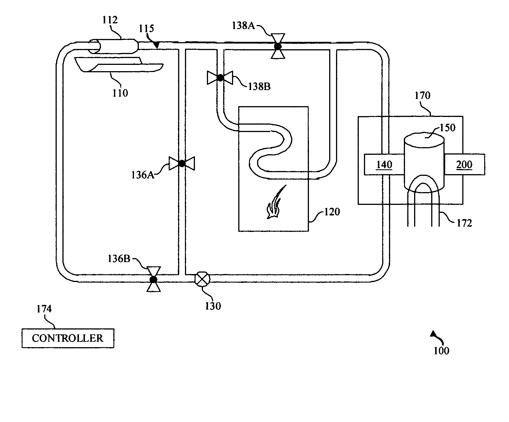
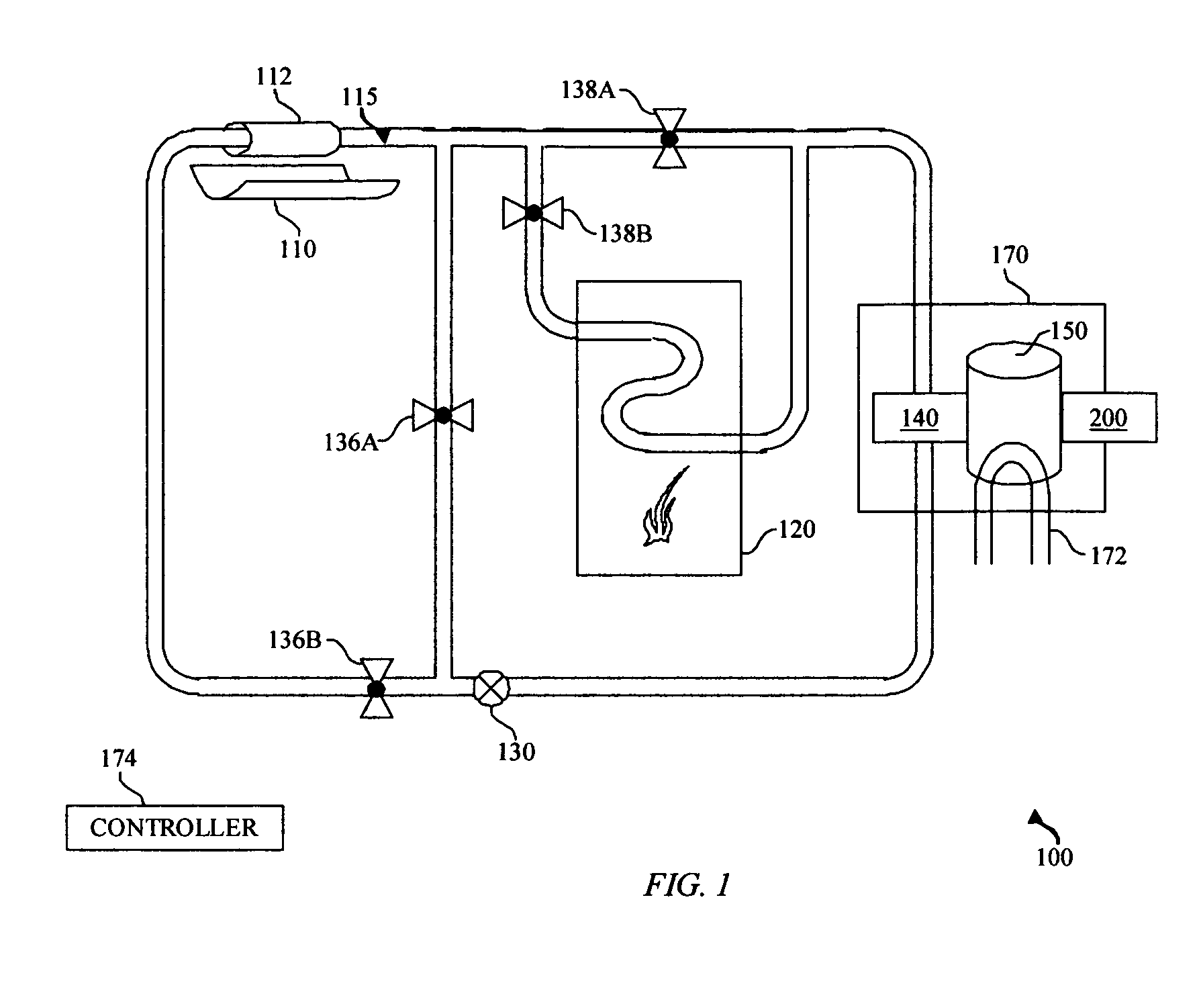
[0020]FIG. 1 is a diagram illustrating a thermal to electric power conversion system 100 in accordance with the present invention. A variety of thermal input energy sources may be used. A parabolic trough solar concentrator 110 may provide a mid grade (around 300 C.) source of thermal energy input. The trough is controlled to track the position of the sun. Energy is focused onto absorber tube 112, which may be comprised of a high absorbtivity, low emissivity material such as dendritic nickel, vacuum insulated, and contain a circulating thermal transfer fluid 115. An example of one such a system is described in more detail in U.S. Pat. No. 5,058,565 “Solar Concentrator Device and Support Structure Therefor”. An alternate embodiment may instead use a high-grade (around 1000 C.) solar thermal source such as a...


PUM


Abstract

A system and method for lower cost, solar thermal generation includes a thermal input block, and an energy storage block.

Description

RELATED APPLICATIONS [0001] This application claims the priority benefit of U.S. Provisional Application Ser. No. 60 / 518,488, entitiled “System and Method for Thermal to Electric Energy Conversion”, filed Nov. 10, 2003.TECHNICAL FIELD OF THE INVENTION [0002] This invention relates generally to the field of solar generation and more specifically to a high reliability, high efficiency, dispatchable, distributed electric generation system. BACKGROUND OF THE INVENTION [0003] The field of solar generation suffers for a variety of reasons, including: poor energy conversion efficiency, high installation cost, high generation cost per watt hour, limited dispatchability, poor energy storage options, variable demand, high maintenance cost, high capital cost, poor reliability, low manufacturing volume, and poor aesthetics. Dispatchability is compromised by environmental factors such as: seasonal cycles, diurnal cycles, temperature, wind, and cloud cover. Efficiency is limited by airborne dust,...

Claims


Application Information

Patent Timeline
Patent Type & Authority Applications(United States)
IPC IPC(8): H01L31/00
CPCF24J2/14H02S10/10H02S10/30F28D20/00F24S23/74F24S90/00F28D20/0056Y02E10/40Y02E10/50Y02E60/14Y02E70/30
Inventor MARSHALL, ROBERT A.
Owner PRACTICAL TECH
Why Eureka
Try Eureka