Amplifier

Active Publication Date: 2005-05-26
CIRRUS LOGIC INC
View PDF7 Cites 36 Cited by
  • Summary
  • Abstract
  • Description
  • Claims
  • Application Information

AI Technical Summary

Benefits of technology

[0032] Advantageously, the generating circuit may comprise a charge pump, which conveniently may be an unregulated capacitor charge pump. Although this gives a noisy generated negative

Problems solved by technology

The physical size of these coupling capacitors is especially significant for portable systems, and their cost is significant for low-cost systems.
This results in annoying clicks and thumps from the speakers or headphones unless special precautions are taken to prevent them.
However, although the use of large coupling capacitors is avoided, the incorporation of the voltage-to-voltage converter clearly increases the complexity, and hence cost, of the amplifier system.
However, a problem with low-cost, simple negative supply generators is that they tend to be noisy (good output voltage regulation, e.g. using a linear post-regulator, which generally requires large decoupling capacitors of its own, would necessitate increased complexity and cost).
Most regulators, especially low-dropout ones, have bandwidths below audio frequency, so it is difficult to suppress audio-frequency components of supply ripple or provide good load regulation at audio frequency without using large decoupling capacitors

Method used


Image

  • Amplifier
  • Amplifier
  • Amplifier

Examples


Example

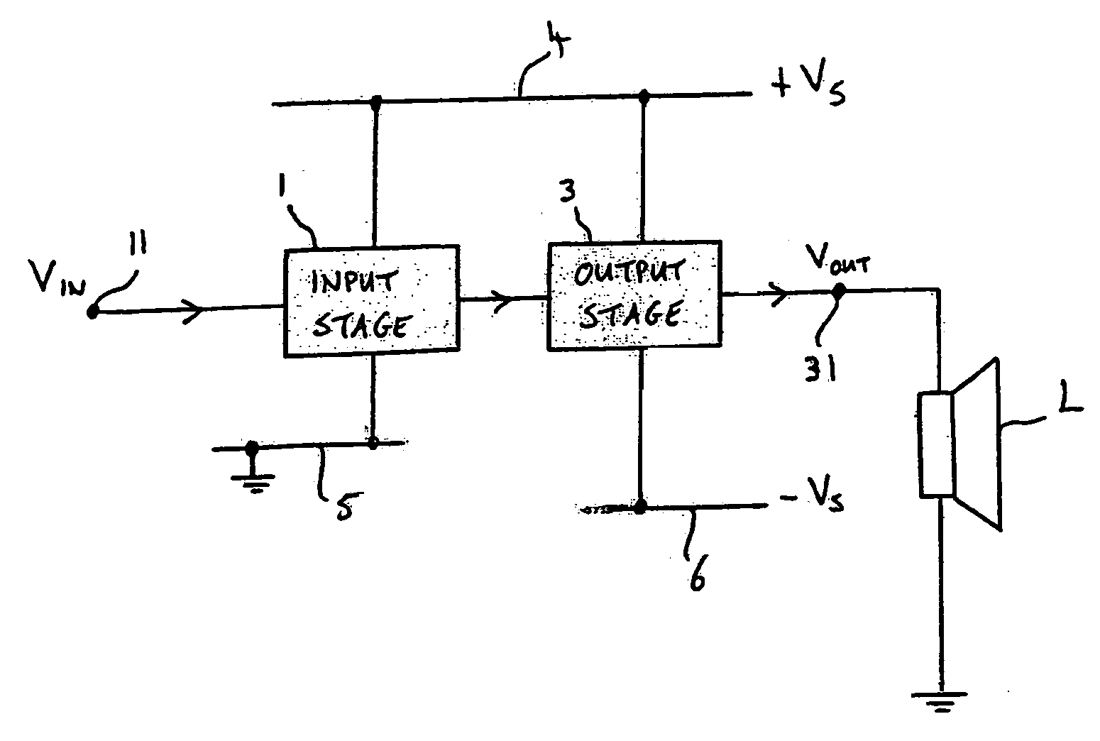
[0051] Referring now to FIG. 1, this shows, in highly schematic form, an amplifier embodying the invention. The amplifier is a two-stage amplifier, having an input stage 1 connected to an output stage 3. The input stage 1 has an input terminal 11 arranged to receive an input signal Vin for amplification. The amplified signal from the input stage is provided to the output stage which in turn generates a corresponding output signal Vout at its output terminal 31. The input stage is a single supply stage, i.e. its power supply connections are between a positive supply rail 4 (to which, in use, a positive supply potential is applied) and a ground rail 5. In contrast, the output stage receives a dual supply—it is connected between the positive supply rail 4 and a negative supply rail 6. In this example, in use the potentials applied to the positive and negative rails are equal in magnitude but opposite in sign (+Vs and −Vs respectively). By operating from this dual polarity supply, the o...


PUM


Abstract

An amplifier is disclosed, having an input stage connected to an output stage. The input stage is connected between a positive supply rail and a ground rail and has an input terminal arranged to receive an input signal. The output stage is connected between a positive supply rail and a negative supply rail and has an output terminal. The output stage is adapted to generate an output signal, which is dependent on a received input signal, at the output, and is further adapted such that, in use, a quiescent voltage at the output terminal is at a selected value between a voltage on the positive supply rail and a voltage on the negative supply rail. For driving a grounded load, the quiescent output voltage is preferably zero volts. In preferred embodiments, the input and output stages are formed on a common substrate using CMOS technology, the output stage including one or more NMOS devices having a triple-well structure. A corresponding method of driving a grounded load is also disclosed.

Description

FIELD OF THE INVENTION [0001] The present invention relates to amplifiers, and in particular, although not exclusively, to audio amplifiers suitable for incorporation with complex other digital or analog circuits on a single integrated circuit, for driving speakers or headphones connected to ground. BACKGROUND TO THE INVENTION [0002] Many integrated audio amplifiers use a single supply (at supply voltage Vdd, typically 5V) and generate an output signal with quiescent voltage of about Vdd / 2. Thus a.c. coupling is needed to provide an output signal referenced to ground, as required for connection to other equipment or speakers or headphones connected to ground. For low impedance loads such as speakers or headphones, these a.c. coupling capacitors need to be big to maintain good bass response (for driving a 16 ohm load, a 470 uF coupling capacitor is required for a −3 dB point at 20 Hz). The physical size of these coupling capacitors is especially significant for portable systems, and ...

Claims


Application Information

Patent Timeline
IPC IPC(8): H03F3/04H03F3/181H03F3/213H03F3/30H04R5/04
CPCH03F3/301H03F3/213H03F3/3023H03F3/3027
Inventor RICHARD, PATRICK E.PENNOCK, JOHN L.
Owner CIRRUS LOGIC INC
Why Eureka
Try Eureka