Tightly coupled and scalable memory and execution unit architecture

a memory and execution unit technology, applied in the field of tightly coupled and scalable memory and execution unit architecture, can solve the problem that data transfer at the memory interface remains a relative bottleneck, and achieve the effect of improving the efficiency of operation

Inactive Publication Date: 2005-05-26
SAMSUNG ELECTRONICS CO LTD
View PDF9 Cites 20 Cited by
  • Summary
  • Abstract
  • Description
  • Claims
  • Application Information

AI Technical Summary

Benefits of technology

[0009] In view of the foregoing background, the present invention is directed to improved hardware architectures for improved access to a memory array and, more specifically, is directed to “memory-centric” methods and apparatus for improved performance in the interface between a memory array and high speed computational engines, such as digital signal processing or “DSP” systems. As mentioned above, improvements in computational performance have been achieved by providing special arithmetic units or “execution units” that are optimized to carry out the arithmetic operations that are commonly required by complex algorithms—mainly multiplication and addition—at very high speed. One example of such an execution unit is the “DAU” (data execution unit) provided in the WE DSP32C chip from AT&T, for DSP applications. The AT&T execution unit, and others like it, provide relatively fast, floating point arithmetic operations to support computation-intensive applications such as speech, graphics and image processing.
[0010] While many improvements have been made in floating-point execution units, pipelined architectures, decreased cycle times, etc., known computational systems generally utilize standard memory systems. For example, DRAM integrated circuits are used for reading input data and, on the output side, for storing output data. Operand and result data is moved into and out of the DRAM memory systems using known techniques such as multiple-ported memory, DMA hardware, buffers, and the like. While such systems benefit from improvements in memory speed and density, data transfer at the memory interface remains a relative bottleneck. I have reconsidered these known techniques and discovered that significant gains in performance and flexibility can be achieved by focusing on the memory, in addition to the execution unit, and by providing improvements in methods and circuits for moving data efficiently among data sources (such as a host processor bus or I / O channel), memory subsystems, and execution units. Since the focus is on the memory, I coined the term “memory-centric” computing.

Problems solved by technology

While such systems benefit from improvements in memory speed and density, data transfer at the memory interface remains a relative bottleneck.

Method used


Image

  • Tightly coupled and scalable memory and execution unit architecture
  • Tightly coupled and scalable memory and execution unit architecture
  • Tightly coupled and scalable memory and execution unit architecture

Examples


Embodiment Construction

FIG. 1

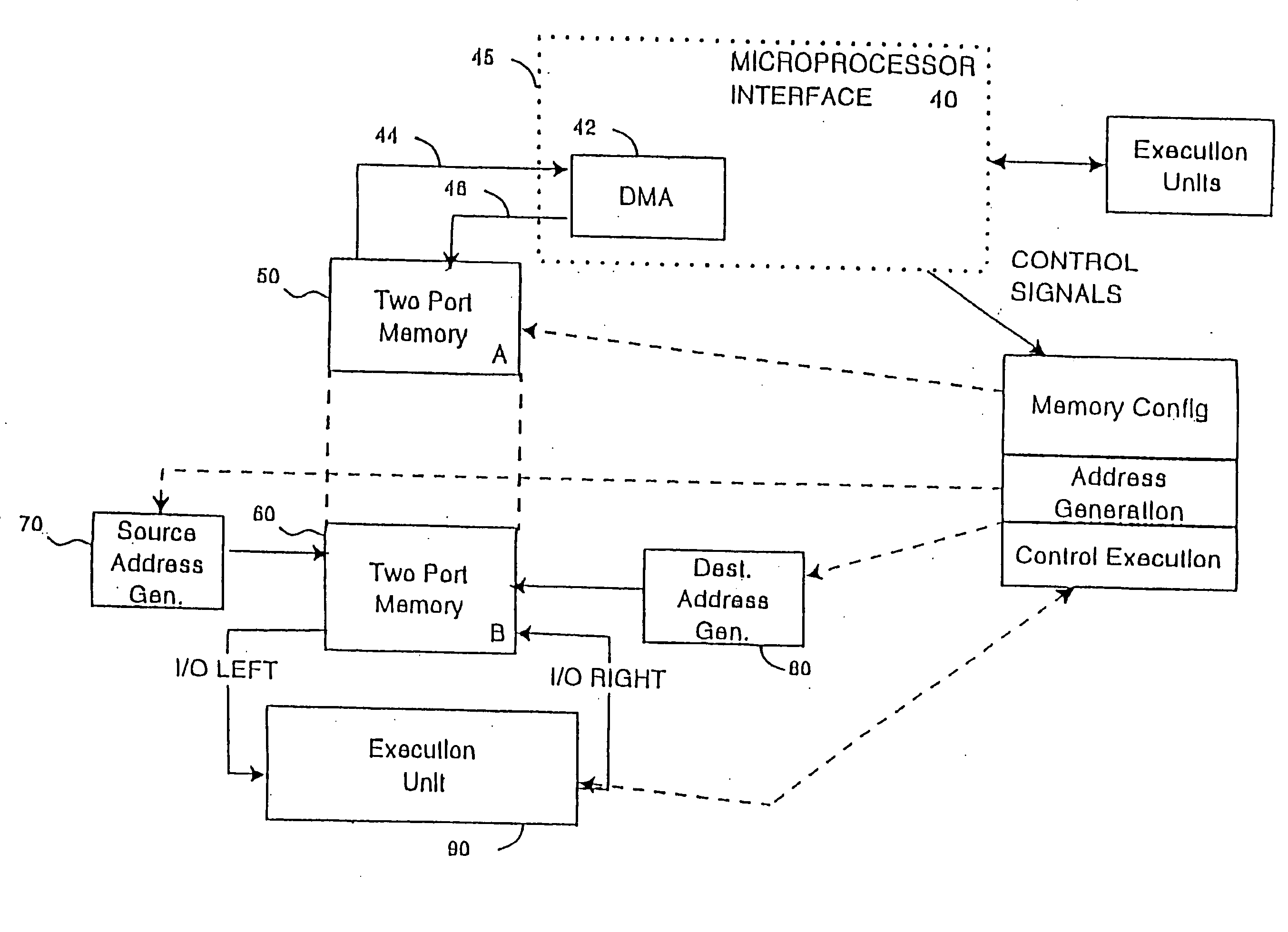
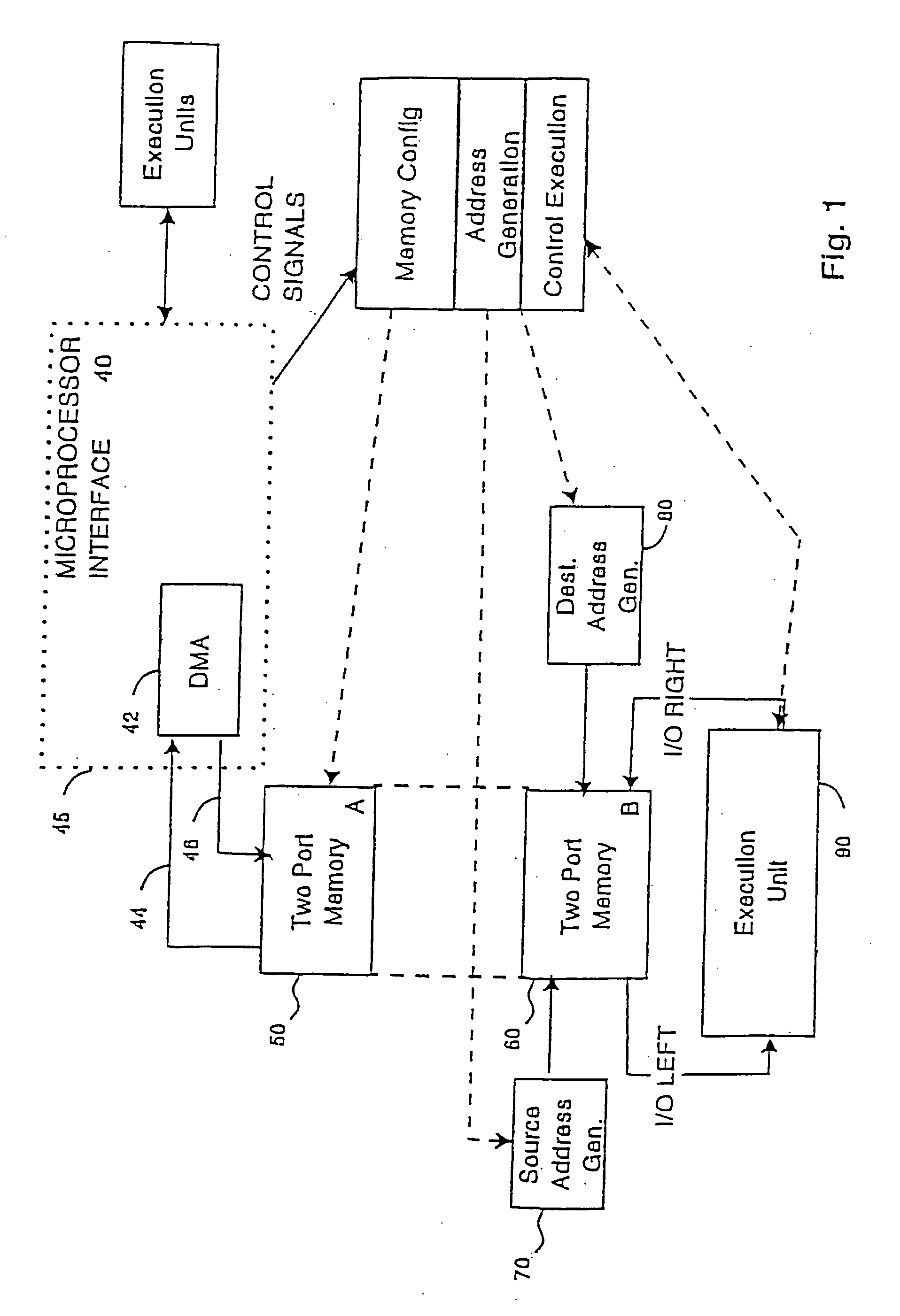
[0073]FIG. 1 is a system-level block diagram of an architecture for memory and computing-intensive applications such as digital signal processing. In FIG. 1, a microprocessor interface 40 includes a DMA port 42 for moving data into a memory via path 46 and reading data from the memory via path 44. Alternatively, a single, bi-directional port could be used. The microprocessor interface 40 generically represents an interface to any type of controller or microprocessor. The interface partition indicated by the dashed line 45 in FIG. 1 may be a physical partition, where the microprocessor is in a separate integrated circuit, or it can merely indicate a functional partition in an implementation in which all of the memory and circuitry represented in the diagram of FIG. 1 is implemented on board a single integrated circuit. Other types of partitioning, use of hybrid circuits, etc., can be used. The microprocessor interface (DMA 42) also includes control signals indicated at 52. The ...


PUM


Abstract

An architecture is shown where an execution unit is tightly coupled to a shared, reconfigurable memory system. Sequence control signals drive a DMA controller and address generator to control the transfer of data from the shared memory to a bus interface unit (BIU). The sequence control signals also drive a data controller and address generator which controls transfer of data from the shared memory to an execution unit interface (EUI). The EUI is connected to the execution unit operates under control of the data controller and address generator to transfer vector data to and from the shared memory. The shared memory is configured to swap memory space in between the BIU and the execution unit so as to support continuous execution and I / O. A local fast memory is coupled to the execution unit. A local address generator controls the transfer of scalar data between the local fast memory and the execution unit. The execution unit, local fast memory and local address generator form a fast memory path that is not dependent upon the slower data path between the execution unit and shared memory. The fast memory path provides for fast execution of scalar operations in the execution unit and rapid state storage and retrieval for operations in the execution unit.

Description

[0001] This application is a divisional of U.S. patent application Ser. No. 09 / 174,057, filed Oct. 16, 1998, now pending, which is a continuation-in-part of co-pending application Ser. No. 08 / 869,277, filed Jun. 4, 1997, claims the priority date of provisional application Ser. No. 60 / 062,431, filed Oct. 16, 1997, which are incorporated herein by reference in their entirety.FIELD OF THE INVENTION [0002] The present invention is generally in the field of digital computer architectures and, more specifically, is directed to an architecture where an execution unit is tightly coupled to a shared reconfigurable memory. BACKGROUND OF THE INVENTION [0003] General purpose microprocessor cores are known for implementation into integrated circuits for a wide variety of applications. Specialized computation engines which are specifically adapted to perform complex computational algorithms, such as Digital Signal Processing (DSP), are also known. DSP cores are specialized computation engines for...

Claims


Application Information

Patent Timeline
Patent Type & Authority Applications(United States)
IPC IPC(8): G06F9/38H04N7/26H04N7/50
CPCG06F9/3879G06F9/3897H04N19/423H04N19/61G06F2213/0038
Inventor COLEMAN, RONLEBACK, BRENTHAWKINSON, STUARTRUBINSTEIN, RICHARD
Owner SAMSUNG ELECTRONICS CO LTD
Why Eureka
Try Eureka