Eureka AIR delivers breakthrough ideas for toughest innovation challenges, trusted by R&D personnel around the world.

Method and apparatus for computing dummy feature density for Chemical-Mechanical Polishing

Active Publication Date: 2005-05-26
SYNOPSYS INC
View PDF1 Cites 15 Cited by
  • Summary
  • Abstract
  • Description
  • Claims
  • Application Information

AI Technical Summary

Benefits of technology

[0018] In a variation on this embodiment, the system efficiently selects panels and computes the dummy feature density by adjusting the characteristic length of the 2-D filter function.
[0022] One embodiment of the present invention provides a system that computes dummy feature density for a CMP (Chemical-Mechanical Polishing) process. Note that the dummy feature density is used to add dummy features to a layout to reduce the post-CMP topography variation. During operation, the system discretizes a layout of an integrated circuit into a plurality of panels. Next, the system computes a feature density and a slack density for the plurality of panels. Note that the feature density for a panel specifies the density of existing features in the panel and the slack density for the panel specifies the maximum density of dummy features that can be added to the panel. Furthermore, in one embodiment of the present invention, the feature density and the slack density are computed for each panel. The system then computes the dummy feature density for the plurality of panels by, iteratively, (a) adjusting the characteristic length of a filter function to obtain an adjusted filter function, and (b) updating the dummy feature density for the plurality of panels using the feature density, slack density, and the adjusted filter function. Note that the filter function models the CMP process. Furthermore, the computed dummy feature density is used to add dummy features to the layout, thereby reducing the post-CMP topography variation. Additionally, adjusting the characteristic length of the filter function improves the effectiveness of the dummy feature density computation in reducing the post-CMP topography variation.
[0024] Moreover, one embodiment of the present invention uses an efficient dummy density assignment method that closely integrates with a low-pass filter CMP model. By utilizing the variance-minimizing heuristic, this embodiment simultaneously assigns dummy densities to multiple panels in each step of the iteration to quickly achieve a substantially-optimal solution.

Problems solved by technology

Although CMP makes the wafer surfaces smoother, it does not completely eliminate topography variations.
If these post-CMP topography variations are too large, they can cause serious problems during subsequent fabrication steps.
For example, these variations can cause defocusing during photolithography, which can result in low fabrication yields and large performance variations.
Hence, the post-CMP topography variations can accumulate over several layers and exacerbate these problems.
Since the underlying metal layer topography is usually not smooth after being patterned, the oxide layer topography is also not smooth.
The oxide feature density non-uniformity affects the CMP process quality.
Unfortunately, these simple rule-based techniques have many shortcomings because they do not accurately model the complex CMP process.
In particular, these techniques can sometimes be ineffective because they add dummy features at suboptimal locations.
Moreover, these techniques can be inefficient because they add more dummy features than necessary.
But, these techniques can be extremely time-consuming.
The computational cost of LP-based methods can become prohibitively high for large layouts with multiple layers.
Consequently, LP-based methods are not practical for many real-life dummy-filling scenarios.
Unfortunately, due to the continuing miniaturization of feature sizes, sub-optimal dummy-fillings are not sufficient to significantly improve yields and reduce performance variations.

Method used


Image

  • Method and apparatus for computing dummy feature density for Chemical-Mechanical Polishing
  • Method and apparatus for computing dummy feature density for Chemical-Mechanical Polishing
  • Method and apparatus for computing dummy feature density for Chemical-Mechanical Polishing

Examples


Embodiment Construction

Integrated Circuit Design and Fabrication

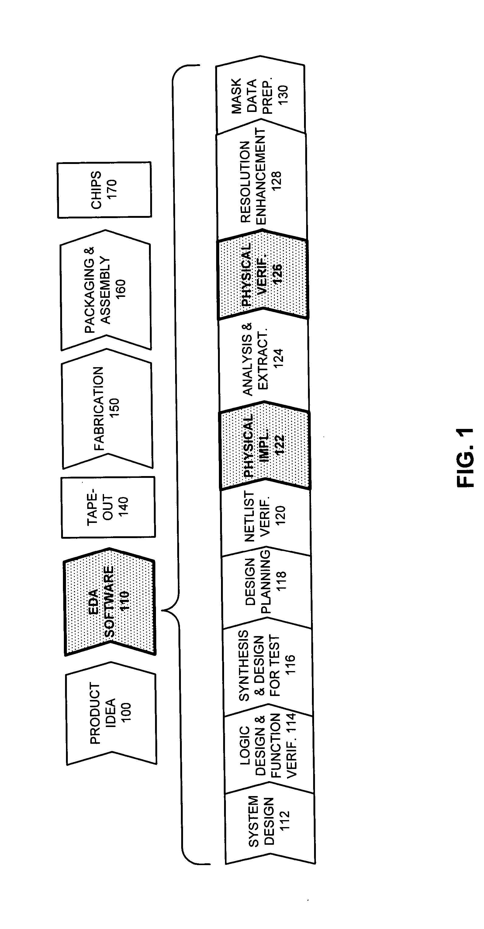
[0034]FIG. 1 illustrates various steps in the design and fabrication of an integrated circuit in accordance with an embodiment of the present invention. The process starts with a product idea (step 100). Next, the product idea is realized using an integrated circuit, which is designed using Electronic Design Automation (EDA) software (step 110). Once the circuit design is finalized, it is taped-out (step 140). After tape-out, the process goes through fabrication (step 150), packaging, and assembly (step 160). The process eventually culminates with the production of chips (step 170).

[0035] The EDA software design step 110, in turn, includes a number of sub-steps, namely, system design (step 112), logic design and function verification (step 114), synthesis and design for test (step 116), design planning (step 118), netlist verification (step 120), physical implementation (step 122), analysis and extraction (step 124), physical verification ...


PUM


Abstract

One embodiment of the present invention provides a system that computes dummy feature density for a CMP (Chemical-Mechanical Polishing) process. Note that the dummy feature density is used to add dummy features to a layout to reduce the post-CMP topography variation. During operation, the system discretizes a layout of an integrated circuit into a plurality of panels. Next, the system computes a feature density and a slack density for the plurality of panels. The system then computes a dummy feature density for the plurality of panels by, iteratively, (a) calculating an effective feature density for the plurality of panels using the feature density and a function that models the CMP process, (b) calculating a filling amount for a set of panels in the plurality of panels using a target feature density, the effective feature density, and the slack density, and (c) updating the feature density, the slack density, and the dummy feature density for the set of panels using the filling amount. In one embodiment of the present invention, the iterative process is guided by a variance-minimizing heuristic to efficiently select the set of panels and assign / remove dummy density to the set of panels to decrease the effective feature density variation.

Description

RELATED APPLICATION [0001] This application hereby claims priority under 35 U.S.C. §119 to U.S. Provisional Patent Application No. 60 / 524,786, filed on 24 Nov. 2003, entitled “Min-variance iterative method for fast smart dummy feature density assignment in chemical-mechanical polishing,” by inventors Xin Wang, Charles Chiang, and Jamil Kawa (Attorney Docket No. 0565).BACKGROUND [0002] 1. Field of the Invention [0003] This invention relates to the process of fabricating semiconductor chips. More specifically, the invention relates to a method and apparatus for computing dummy feature density for performing dummy filling that improves the quality of a Chemical-Mechanical Polishing (CMP) process. [0004] 2. Related Art [0005] The miniaturization of integrated circuits has been a key driving force behind technological innovations. Miniaturization of transistors and interconnects has occurred because of the rapid advances in various fabrication technologies, such as “Chemical Mechanical P...

Claims


Application Information

Patent Timeline
IPC IPC(8): G06F17/50
CPCG06F2217/12G06F17/5068G06F30/39G06F2119/18Y02P90/02
Inventor WANG, XINCHIANG, CHARLES C.KAWA, JAMIL
Owner SYNOPSYS INC
Why Eureka
Eureka Blog
Learn More