Water soluble tooling materials for composite structures

a tooling material and composite technology, applied in the field of new coring and tooling materials for polymer composites, can solve the problems of complex and expensive tooling that is required for their fabrication, limited performance requirements of composite components, and inability to meet the requirements of secondary structures, etc., and achieves the effects of easy washing away from the finished part, easy shaping, and easy water soluble solubl

Inactive Publication Date: 2005-06-02
ADVANCED CERAMICS
View PDF10 Cites 29 Cited by
  • Summary
  • Abstract
  • Description
  • Claims
  • Application Information

AI Technical Summary

Benefits of technology

[0014] The present invention offers alternative coring and tooling system and materials. The present invention offers novel low-cost coring and tooling materials for composite parts. Unlike conventional coring and tooling materials, the materials of the present invention are readily soluble in water and can easily be washed away from the finished part. Furthermore, the coring and tooling materials can be used in the manufacture of a wide range of composite parts that can be cured at higher temperatures than heretofore possible.
[0015] Accordingly, an object of the present invention is to provide a composite coring and tooling material that is cost-effective, enviro...

Problems solved by technology

Initially, composite components were limited to secondary structures such as floorboards and engine cowlings due to limited experience with designing composite structures.
Composite materials also are used in military and defense applications, where the performance requirements may be even more demanding.
A significant drawback to the use of composite structures in aerospace applications, whether commercial or military, is the complicated and expensive tooling that is required for their fabrication.
The difference in the coefficient of thermal expansion of the composite and of the tool can create geometrical inaccuracies as well as residual stresses.
If the tool material has a low thermal conductivity, significant time can be spent simply getting sufficient heat to the composite part.
Thus, curing irregularities can develop between areas of thick and thin tooling.
These irregularities also translate into geometric inaccuracies and residual stresses.
Also, metal mold materials generally require complex and time-consuming machining operations in order to create the tool surface, which further contributes to design complexities.
For larger components, the time required to generate the surface of the tool can become unacceptable.
Additionally, it can be very difficult to make any modifications to metal tooling once made, if changes to a part are subsequently identified.
Although composite-tooling materials may seem ideal due to the matched coefficien...

Method used


Image

  • Water soluble tooling materials for composite structures
  • Water soluble tooling materials for composite structures
  • Water soluble tooling materials for composite structures

Examples


example 1

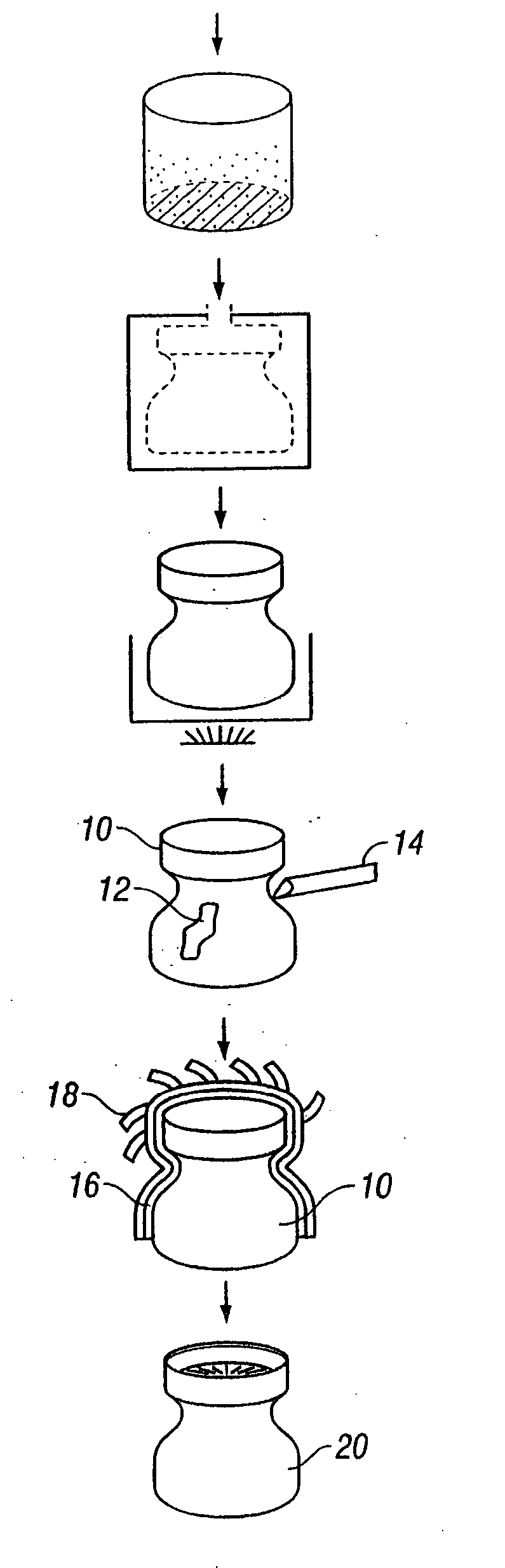
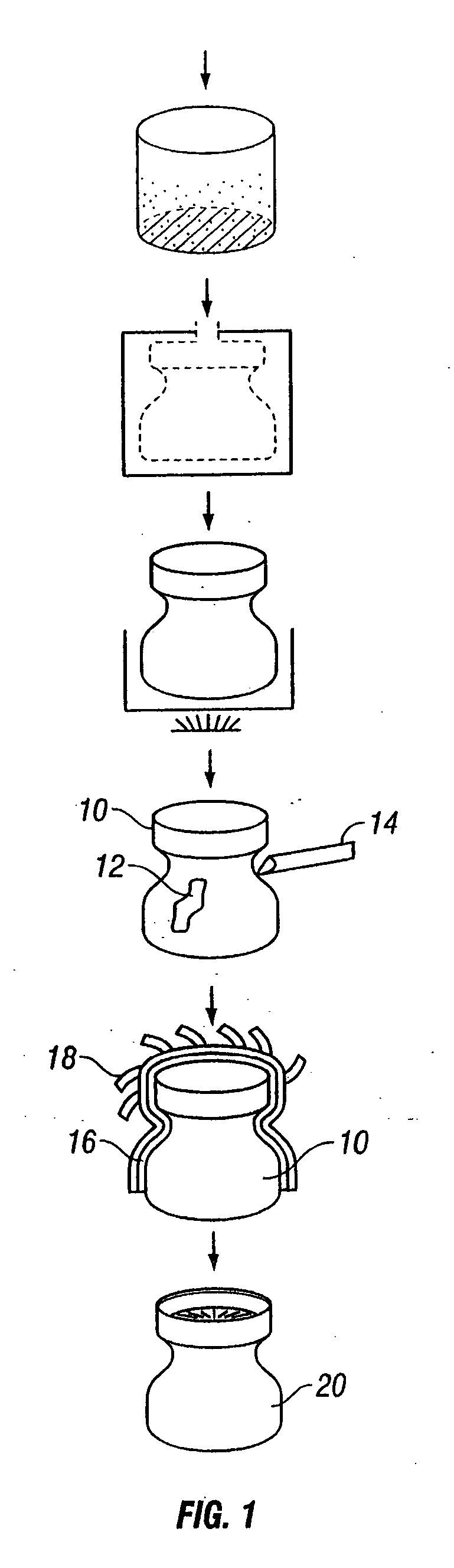
[0043] This example illustrates a composite blend for use as a core form for the fabrication of composite parts. The coring material includes a composite blend of hollow ceramic-microballons and a high thermal stability thermoplastic binder. In preparing the composite blend, the thermoplastic binder is mixed with water to form a first solution. The first solution is subsequently mixed with a ceramic micro-sphere filler to provide a composite blend in the form of a moist, formable paste. The paste can be shaped and dried in a drying oven at between about 100 to about 125° C. for about 1 hour per inch of thickness. The dried paste form can be subsequently machined as desired, thereby producing a mandrel or core having a desired configuration. Examples of composite blends containing PVP and ceramic microsphere filler are shown in Tables 1 and 2.

TABLE 1Wt.(lbs.)Wt. %SolutionPVP K900.2415%Water1.485%Total1.60100% PasteSolution1.6020%Extendospheres SLG6.4080%Total8.00100% 

[0044]

TABLE 2W...

example 2

[0047] This example illustrates a composite blend for use as a tooling material for fabrication of composite parts. The tooling material comprises a composite blend having a high thermal stability thermoplastic binder and either metal filler or high conductivity ceramic filler. The metallic or ceramic fillers used in the composite blend increase the overall thermal conductivity of the blend, and thus, provide a tooling material that can be tailored to provide specific values of thermal expansion and heat transfer. Conventional tooling materials, although inexpensive, are inferior due to their inability to have tailored coefficient of thermal expansion and thermal conductivity.

[0048] High conductivity ceramic fillers, such as graphite, alumina, and silicon carbide, can be used in the present invention. Tables 3 and 4 illustrate composite blends containing PVP and graphite powder. Note, composite blends having graphite powder as the ceramic filler require dispersants for the graphite...

example 3

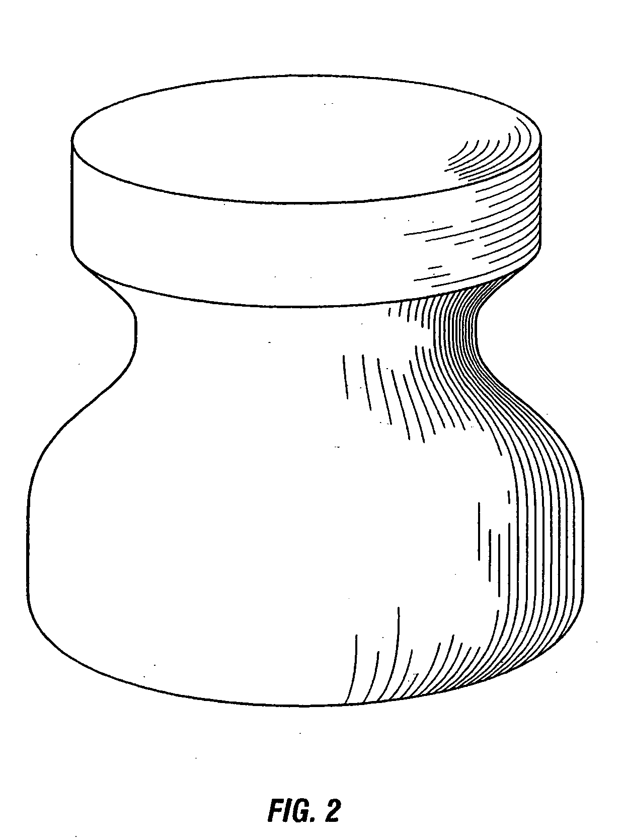
[0052] This example illustrates formation of a mandrel and its ability to be machined. A mandrel, as shown in FIG. 2, has a specific gravity of 0.3 (dry) and 0.8 (wet). The important properties are shown in Table 5.

TABLE 5PropertyValueCompressive Strengthapproximately 700-1000psiDensity28.1lbs / ft3 (wet)23.1lbs / ft3 (dry)Coefficient of Thermal6 × 10−6in / in ° C.Expansion


PUM

PropertyMeasurementUnit
Temperatureaaaaaaaaaa
Viscosityaaaaaaaaaa
Shapeaaaaaaaaaa

Abstract

The present invention relates to a low density, water-soluble coring and tooling material used for the fabrication of composite parts. One aspect of the present invention relates to a lightweight, strong composite coring material that can be easily shaped and removed from cured composite parts. Another aspect of the present invention relates to a lightweight, strong composite tooling material that is easily tailored to provide a specific coefficient of thermal expansion and thermal conductivity, thus providing a tooling material that can be matched to the composite structure and material being fabricated.

Description

CROSS REFERENCE TO RELATED APPLICATIONS [0001] This application is a divisional of U.S. patent application Ser. No. 10 / 092,843, filed Mar. 6, 2002, entitled “Water Soluble Tooling Material For Composite Structures, which is based on, and claims the benefit of, U.S. Provisional Application No. 60 / 274074, filed on Mar. 7, 2001, entitled “Water Soluble Tooling Material For Composite Structures.”[0002] The present invention was made with U.S. Government support under grant Number N68335-01-C-0053 awarded by the Naval Air Warfare Center. Accordingly, the Government may have certain rights in the invention described herein.FIELD OF THE INVENTION [0003] The present invention relates to a novel coring and tooling material for polymer composites. Particularly, the present invention relates to a low-density, water-soluble composite blend used to form a core material for the fabrication of composite parts. In addition, the present invention relates to a low density, water-soluble composite ble...

Claims


Application Information

Patent Timeline
IPC IPC(8): B22C9/04B22C7/02B28B7/34B28B7/46
CPCB28B7/46B28B7/342
Inventor ARTZ, GREGORY J.LOMBARDI, JOHN L.VAIDYANATHAN, K. RANJIWALISH, JOSEPH
Owner ADVANCED CERAMICS
Why Eureka
Try Eureka