Light-emitting element and light-emitting device using the same

a technology of light-emitting devices and light-emitting elements, which is applied in the direction of discharge tube luminescence screens, discharge tube/lamp details, electric discharge lamps, etc., can solve the problems of poor bondability between metal electrodes, short emission lifetime, and poor organic compound layer bondability, and achieve efficient emission and stable luminescence.

Inactive Publication Date: 2005-06-02
SEMICON ENERGY LAB CO LTD
View PDF22 Cites 88 Cited by
  • Summary
  • Abstract
  • Description
  • Claims
  • Application Information

AI Technical Summary

Benefits of technology

[0009] Accordingly, an object of the present invention is to provide a light-emitting element in which light is emitted efficiently and stable luminescence can be obtained for a long stretch of time. In addition, a light-emitting element to which a material that does not require a high technique during manufacturing the light-emitting element is applied and which is applicable to the mass production is provided.
[0010] As a result of repeating keen examination, the inventors found that light is emitted efficiently and stable luminescence can be obtained for a long stretch of time in a light-emitting element containing bismuth oxide, cobalt oxide, chromium oxide, copper oxide, nickel oxide, or titanium oxide. Therefore, a plurality of layers is sandwiched between a pair of electrodes in the invention, and a light-emitting element mainly utilizing an organic compound as a luminous body has a layer containing bismuth oxide, cobalt oxide, chromium oxide, copper oxide, nickel oxide, or titanium oxide.
[0011] Bismuth oxide, cobalt oxide, chromium oxide, copper oxide, nickel oxide, and titanium oxide have good adhesiveness with a metal film, a metallic oxide film, or the like that functions as an electrode of the light-emitting element. Furthermore, they have good adhesiveness with an organic compound.

Problems solved by technology

Although luminescence having high luminance can be obtained, there is a defect that an emission lifetime is short.
As these factors, it can be considered that bondability between a metal electrode and a film during lamination, for example, an organic compound layer is not good due to electric conduction for a long time.
Although the light-emitting element using an alkali metal has favorable efficiency, the alkali metal needs to be treated with religious care since it is easily oxidized; therefore, there is a problem that it is difficult to use the alkali metal for manufacturing a light-emitting element.
However, although luminous efficiency can be improved compared with a light-emitting element using an MgAg alloy known as a cathode with a low work function, there is a problem that the adhesiveness with an organic thin film is poor and stable luminescence cannot be easily obtained.

Method used


Image

  • Light-emitting element and light-emitting device using the same
  • Light-emitting element and light-emitting device using the same
  • Light-emitting element and light-emitting device using the same

Examples


embodiment mode 1

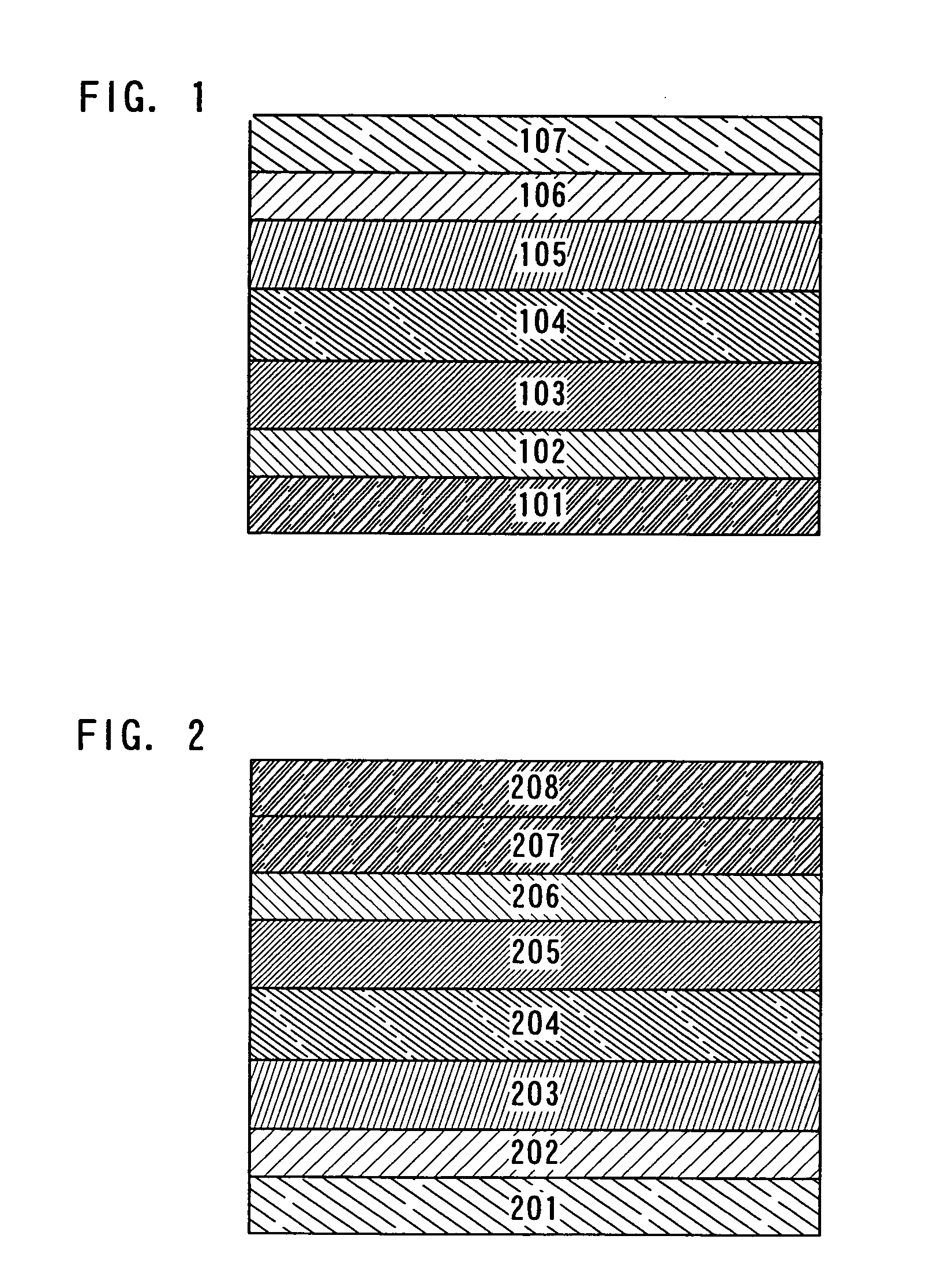
[0036] An element structure of a light-emitting element of the present invention is explained with reference to FIG. 1.

[0037] The light-emitting element of the invention has a structure in which a plurality of layers is sandwiched between a pair of electrodes. The plurality of layers is formed by laminating a layer comprising a substance with high carrier transportability, a substance with high carrier injectability, or the like and a layer containing a substance selected from bismuth oxide, cobalt oxide, chromium oxide, copper oxide, nickel oxide, and titanium oxide in combination so that a light-emitting region is formed in the part separated from each electrode.

[0038] Specifically, the light-emitting element of the invention has a structure in which a first layer 102 containing a substance selected from bismuth oxide, cobalt oxide, chromium oxide, copper oxide, nickel oxide, and titanium oxide is provided to be in contact with a first electrode 101; a second layer 103 comprisin...

embodiment mode 2

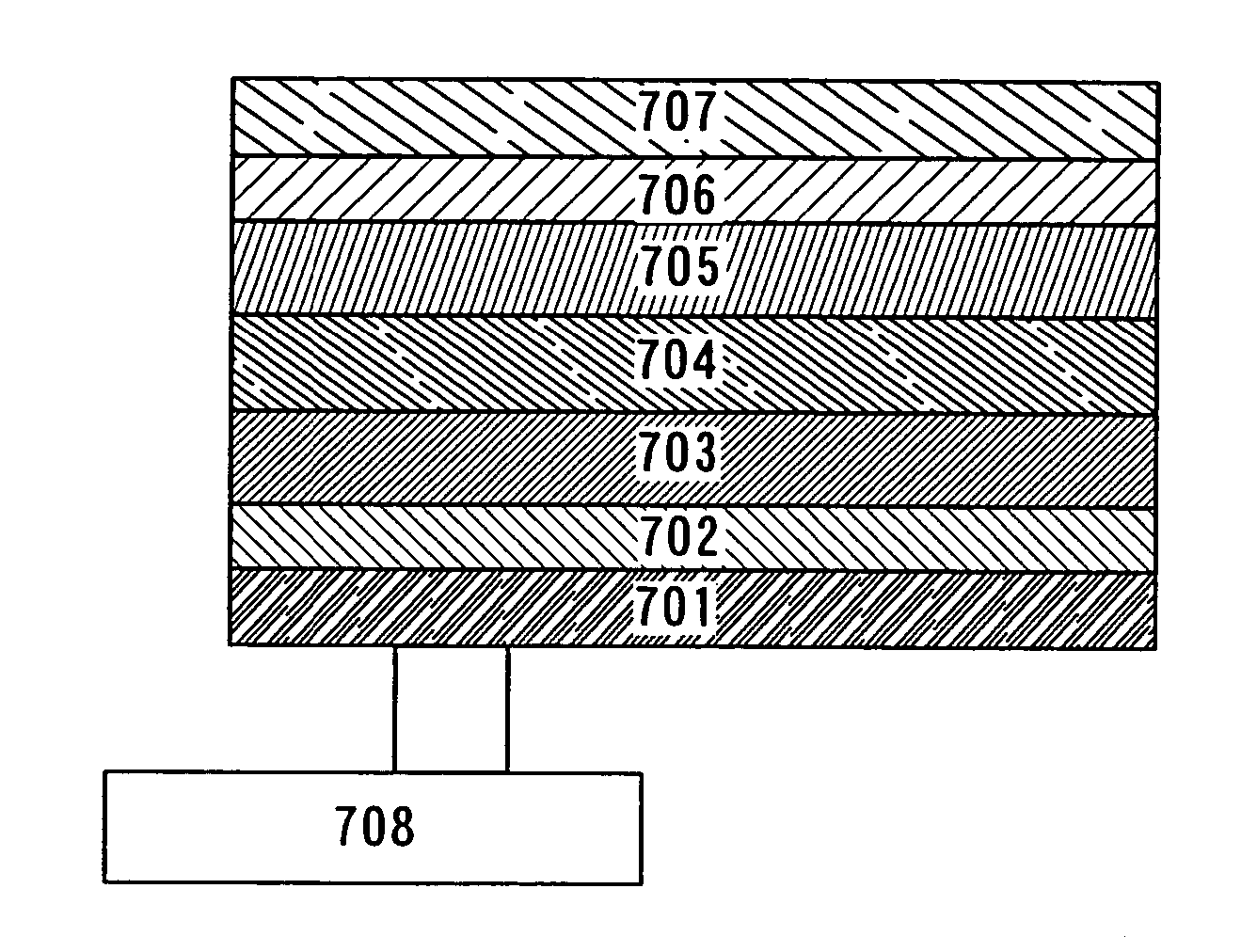
[0048] In this embodiment mode, a light-emitting element having a different laminated structure from that shown in Embodiment Mode 1 is explained with reference to FIG. 2.

[0049] A light-emitting element of this embodiment mode has a structure in which a first layer 202 containing a substance selected from bismuth oxide, cobalt oxide, chromium oxide, copper oxide, nickel oxide, and titanium oxide is provided to be in contact with a first electrode 201; a second layer 203 comprising a substance with high electron transportability is provided to be in contact with the first layer 202; a third layer 204 containing a light-emitting substance is provided to be in contact with the second layer 203; a fourth layer 205 comprising a substance with high hole transportability is provided to be in contact with the third layer 204; a fifth layer 206 containing a substance selected from bismuth oxide, cobalt oxide, chromium oxide, copper oxide, nickel oxide, and titanium oxide is provided to be i...

embodiment mode 3

[0053] There is no specific restriction on an element structure of a light-emitting element of the present invention, and it can be appropriately selected depending on the object. Basically, it is a structure in which layers containing light-emitting substances (formed by appropriately combining: a hole injection layer, a hole transport layer, a first mixed layer of a hole transport material and a light-emitting material, a light-emitting layer, a second mixed layer of a light-emitting material and an electron transport material, a hole blocking layer, an electron transport layer, an electron injection layer, and the like) are sandwiched between a pair of electrodes (an anode and a cathode). In the invention, a slash sign will be defined as hereinafter. A laminating order as described A / B / C means A is formed at first, subsequently B is formed over A, and then C is laminated over B. For example, a light-emitting element having the following structure is given: anode / hole injection la...


PUM


Abstract

It is an object of the invention is to provide a light-emitting element in which failure of the light-emitting element due to separation can be controlled and stable luminescence can be obtained with high-efficiency and for a long stretch of time by controlling separation of layers constituting the light-emitting element. According to one aspect of a light-emitting element of the invention, the light-emitting element sandwiches a plurality of layers between a pair of electrodes, wherein at least one layer of the plurality of layers is a layer containing a substance selected from bismuth oxide, cobalt oxide, chromium oxide, copper oxide, nickel oxide, and titanium oxide, or at least one layer of layers different from a light-emitting layer among the plurality of layers is a mixed region of one substance selected from bismuth oxide, cobalt oxide, copper oxide, magnesium oxide, nickel oxide, zinc oxide, and titanium oxide and an organic compound.

Description

BACKGROUND OF THE INVENTION [0001] 1. Field of the Invention [0002] The present invention relates to a light-emitting element having an anode, a cathode, and a layer containing an organic compound in which luminescence can be obtained by applying an electric field (hereinafter, referred to as a “layer containing a light-emitting substance”), and specifically to a light-emitting element which can achieve long term stabilization. [0003] 2. Description of the Related Art [0004] A light-emitting element (also referred to as an organic or organic-inorganic hybrid electroluminescent element) and a solar battery are given as an example of a photoelectronic device using an organic semiconductor material as a functional organic material. These devices utilize electrical properties (carrier transportability) and optical properties (light absorption or light emission) of organic semiconductor materials, and specifically, the light-emitting element shows remarkable development. [0005] A light-e...

Claims


Application Information

Patent Timeline
Patent Type & Authority Applications(United States)
IPC IPC(8): H01L51/00H01L51/50H05B33/00
CPCH01L51/0059H01L51/0078H01L51/0081H01L51/5096H01L51/5088H01L51/5092H01L51/5048H10K85/631H10K85/311H10K85/324H10K50/14H10K50/17H10K50/171H10K50/18
Inventor YAMAZAKI, SHUNPEINOMURA, RYOJIABE, HIROKO
Owner SEMICON ENERGY LAB CO LTD
Why Eureka
Try Eureka