
Voltage sensor and dielectric material

a dielectric material and voltage sensor technology, applied in the field of voltage sensors, can solve the problems of high frequency response of the device, size, safety and cost, and limitations of the above-referenced prior art, and achieve the effect of high dielectric strength

Inactive Publication Date: 2005-06-09
FIELDMETRICS
View PDF14 Cites 25 Cited by
  • Summary
  • Abstract
  • Description
  • Claims
  • Application Information

AI Technical Summary

Benefits of technology

[0020] An advantage of the present invention is that the dielectric material can have a large dielectric constant.
[0021] Another advantage of the present invention is that the dielectric material properties do not vary appreciably over temperature or time.
[0022] Another advantage of the present invention is that the dielectric strength can be high.
[0023] Another advantage of the present invention is that by using polymeric film / foil capacitors in the individual impedance elements, the dielectric has a graceful failure mode when internal dielectric breakdown occurs.
[0024] Another advantage of the present invention is that the dielectric can have a dielectric constant that varies in a designated manner as a function of direction in the solid.
[0025] Another advantage of the present invention is that the dielectric can have a dielectric constant that varies in a designated manner as a function of position in the solid or on the surface of the solid.

Problems solved by technology

The above-referenced prior art has one or more limitations in measurement performance, size, safety and cost.
Inductive voltage transformers and capacitive voltage transformers use insulating polymeric solids, insulating oil or sulfur hexafluoride gas for insulation, resulting in a heavy or expensive device.
The high resistance, when combined with the distributed capacitance of the structure, causes the high frequency response of the device to be limited.
Capacitive voltage dividers can fail catastrophically if the elements comprising the divider fail in the short circuit condition.
Large voltage transients with respect to time, or dV / dt, can cause a pure capacitive divider to fail because of the large displacement current that flows through the device.
Line integral optical voltage sensors are physically small to keep costs affordable, and as a result they require insulating fluids and expensive housings to support the large electric fields near the sensor element.
For example, water vapor condensing on the electric field sensor will cause large errors in measurement.
An expensive and continuously monitored housing is required to maintain the dry, insulating environment required for this approach.
Composite materials comprised of a polymer or ceramic host and powdered filler with a high dielectric constant have large temperature dependencies, high loss tangents, poor stability over time, and a reduced dielectric constant compared to the filler's dielectric constant.
Single crystals of high dielectric constant materials such as Barium Titanate have dielectric constants that vary with direction in the crystal, but they are not easily adjustable.
Single crystals are also very expensive and difficult to machine to a desired shape.

Method used


Image

  • Voltage sensor and dielectric material
  • Voltage sensor and dielectric material
  • Voltage sensor and dielectric material

Examples


Embodiment Construction

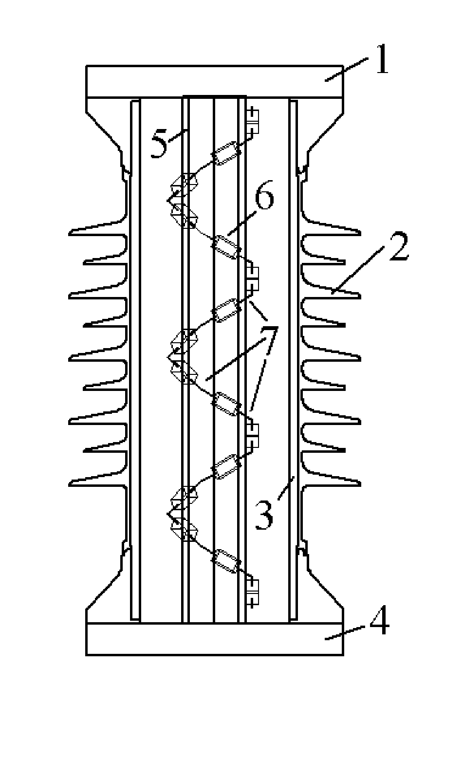
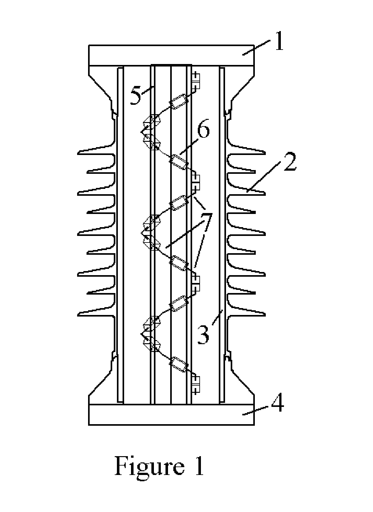
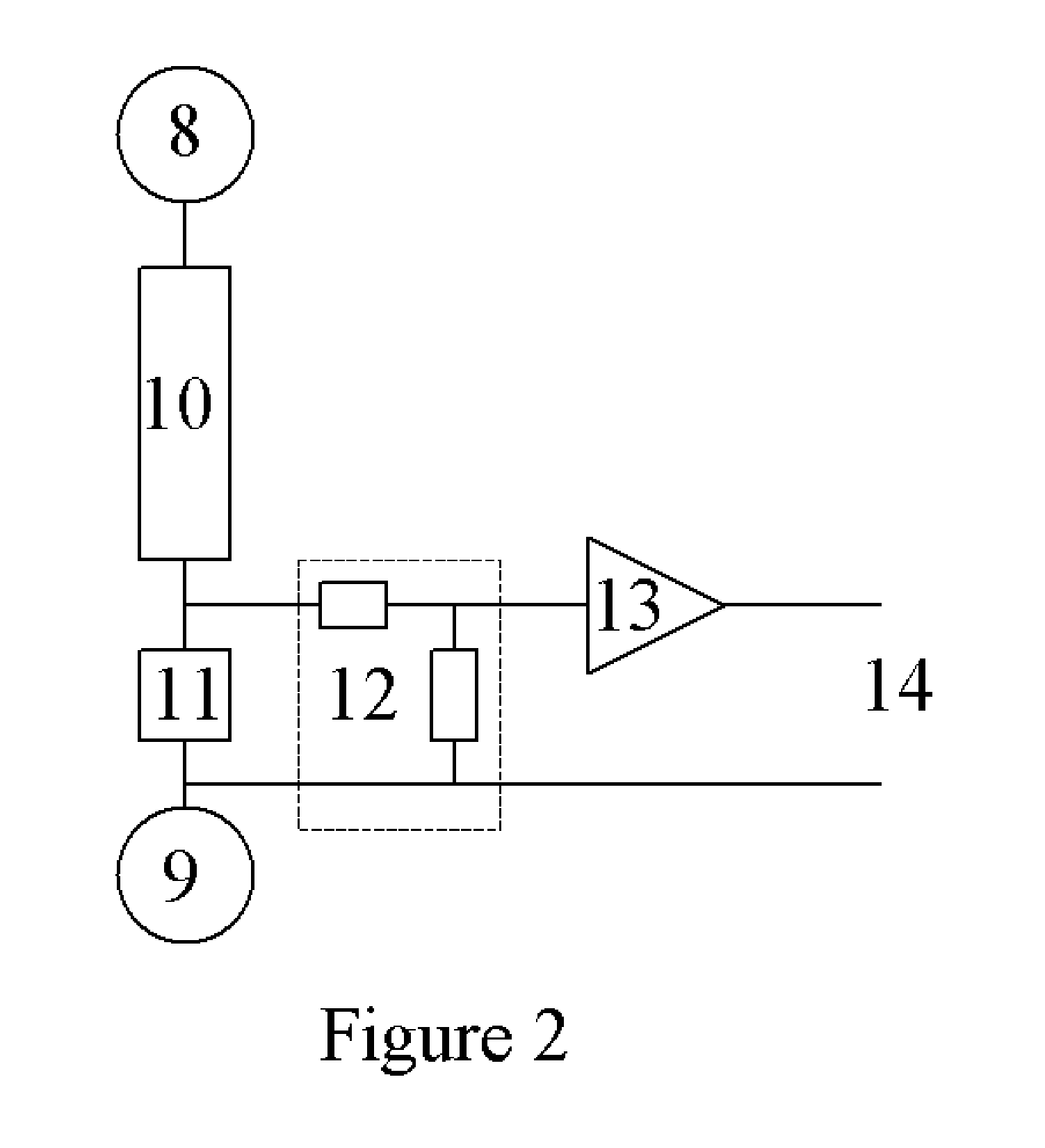
[0028] A voltage sensor is described (shown in FIG. 1) that uses a plurality of impedances 6 connected in series between two conductors 1 and 4 at different electrical potentials. An output signal is provided by measuring the voltage across one of the impedance elements at one or both ends of each string. The impedances 6 are selected to meet particular performance criteria that depend on the application of the divider. The sensor consists of one or more strings of impedances 7 that are fastened to an insulating support tube 5. The divider structure is contained within an insulating housing 3 made from porcelain or polymer with weather sheds 2 on the exterior surface. The strings are distributed in an optimal fashion for voltage grading, with the preferred embodiments being straight sections, or coiled shapes having cross sections including but not limited to circular or square. Each string starts at a different angular location at the top of the tube. For example, if two strings ar...


PUM


Abstract

A voltage sensor is described that consists of an arrangement of impedance elements. The sensor is optimized to provide an output ratio that is substantially immune to changes in voltage, temperature variations or aging. Also disclosed is a material with a large and stable dielectric constant. The dielectric constant can be tailored to vary with position or direction in the material.

Description

CROSS REFERENCE TO PRIOR APPLICATION [0001] This application claims the priority of U.S. Provisional Application Ser. No. 60 / 481,739 filed Dec. 4, 2003 and entitled “VOLTAGE SENSOR AND DIELECTRIC MATERIAL”, the subject matter of which is incorporated herein by reference.FEDERAL GOVERNMENT STATEMENT [0002] This invention was made with Government support under contract DE-FG03-01 ER83228 awarded by the Department of Energy. The Government has certain rights to this invention.FIELD OF THE INVENTION [0003] The present invention relates to a voltage sensor for measuring voltage such as the voltage of a high-voltage power transmission line. The present invention also relates to an insulating material for use in electrical apparatus where the material is required to have stable dielectric properties when exposed to an electric field. DESCRIPTION OF THE PRIOR ART [0004] A variety of high-voltage measurement techniques are known in the art, including voltage transformers, capacitive voltage ...

Claims


Application Information

Patent Timeline
Patent Type & Authority Applications(United States)
IPC IPC(8): G01R15/06G01R15/14
CPCG01R15/14G01R15/06
Inventor YAKYMYSHYN, CHRISTOPHER PAULYAKYMYSHYN, PAMELA JANEBRUBAKER, MICHAEL ALLEN
Owner FIELDMETRICS
Learn More