
Electro-optic assemblies and materials for use therein

a technology of optical assemblies and materials, applied in the direction of instruments, film/foil adhesives, non-macromolecular adhesive additives, etc., can solve the problems of preventing their widespread use, imposing stringent requirements on lamination adhesives, and inadequate service life of these displays

Inactive Publication Date: 2005-06-09
VERSUM MATERIALS US LLC
View PDF99 Cites 63 Cited by
  • Summary
  • Abstract
  • Description
  • Claims
  • Application Information

AI Technical Summary

Benefits of technology

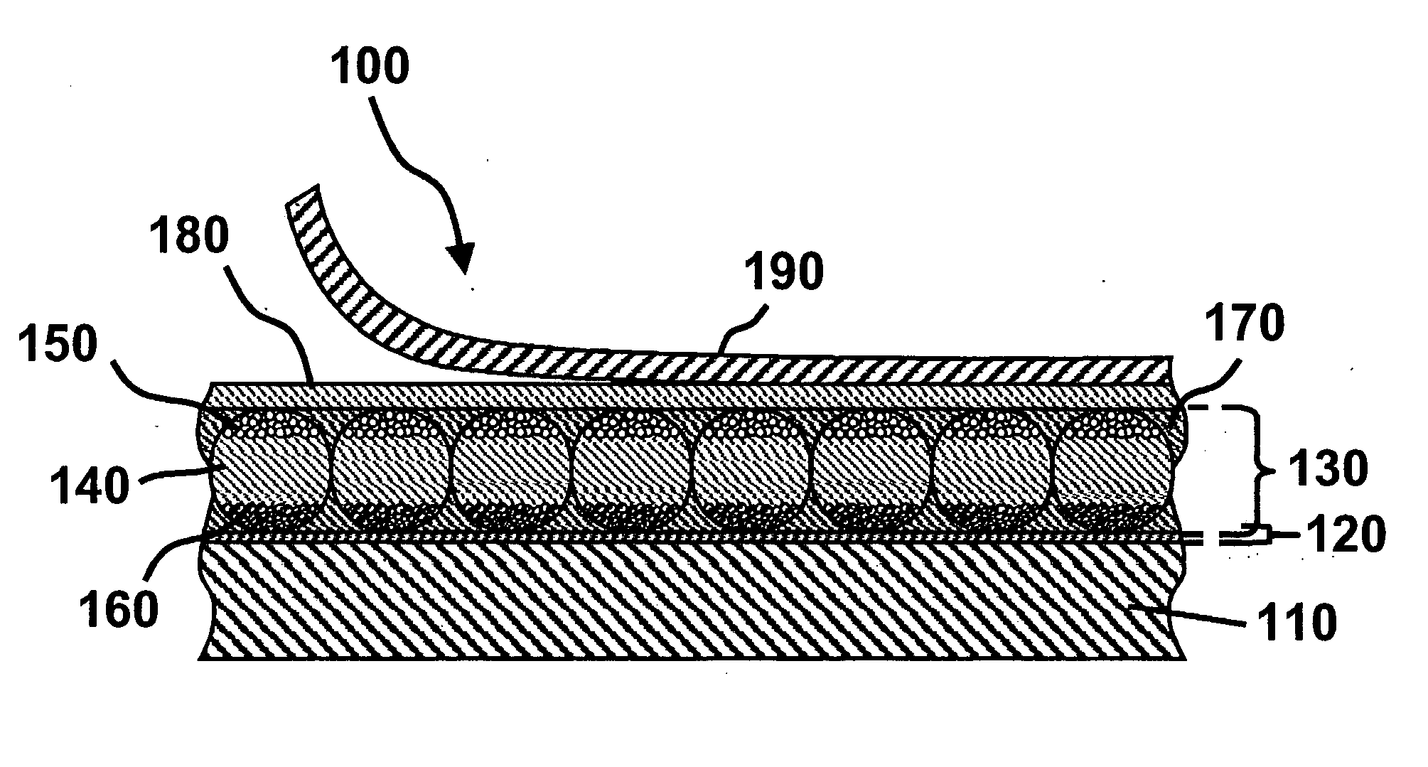
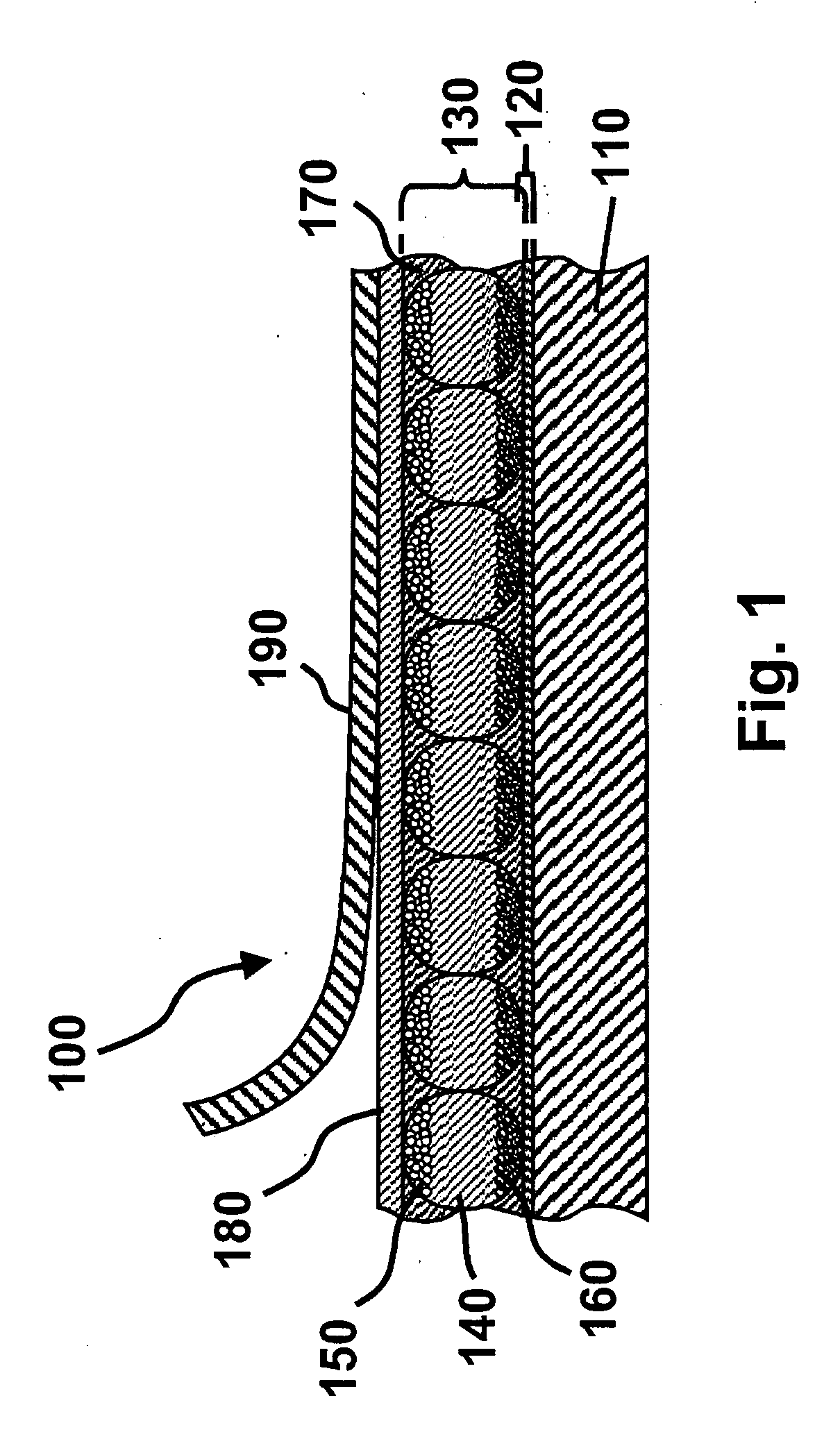
The patent text describes an electro-optic assembly comprising a layer of adhesive material and a layer of electro-optic material. The adhesive layer contains a mixture of a polymeric adhesive material and an additive selected from a salt, a polyelectrolyte, a polymer electrolyte, a solid electrolyte, and combinations thereof. The adhesive layer can provide functions besides adhesion, such as color filtering or optical biasing. The electro-optic assembly can be used in various applications such as displays or light-transmissive electrically-conductive layers. The patent also describes an article of manufacture comprising a solid electro-optic medium with adhesive layers on its surfaces. The adhesive layers can be made of a mixture of a polymeric adhesive material and an additive such as a salt, a polyelectrolyte, a polymer electrolyte, or a solid electrolyte. The patent also describes an elephoretic medium comprising capsules and a binder containing a mixture of a polymeric adhesive material and an additive such as a salt, a polyelectrolyte, a polymer electrolyte, or a solid electrolyte. The binder can be made of a mixture of a polymeric adhesive material and an additive such as a conductive metal powder, a ferrofluid, a non-reactive solvent, a conductive organic compound, or a combination of these additives. The patent also describes the use of the electro-optic assembly in various applications such as displays or light-transmissive electrically-conductive layers.

Problems solved by technology

Nevertheless, problems with the long-term image quality of these displays have prevented their widespread usage.
For example, particles that make up electrophoretic displays tend to settle, resulting in inadequate service-life for these displays.
However, vacuum lamination of the two parts of an electro-optic display in this manner imposes stringent requirements upon the lamination adhesive used, especially in the case of a display using an encapsulated electrophoretic medium.
The lamination adhesive should have adequate flow properties at the lamination temperature to ensure high quality lamination, and in this regard, the demands of laminating encapsulated electrophoretic and some other types of electro-optic media are unusually difficult; the lamination has be conducted at a temperature of not more than about 130° C. since the medium cannot be exposed to substantially higher temperatures without damage, but the flow of the adhesive must cope with the relatively uneven surface of the capsule-containing layer, the surface of which is rendered irregular by the underlying capsules.
The lamination temperature should indeed be kept as low as possible, and room temperature lamination would be ideal, but no commercial adhesive has been found which permits such room temperature lamination.
As discussed in detail in the aforementioned copending application Ser. No. 10 / 064,389, a lamination adhesive used in an electro-optic display should meet certain electrical criteria, and this introduces considerable problems in the selection of the lamination adhesive.
However, in such applications, the electrical properties of the lamination adhesive are not relevant, and consequently the commercial manufacturers pay no heed to such electrical properties.
If the resistivity of the adhesive layer is too high, a substantial voltage drop will occur within the adhesive layer, requiring an increase in voltage across the electrodes.
Increasing the voltage across the electrodes in this manner is undesirable, since it increases the power consumption of the display, and may require the use of more complex and expensive control circuitry to handle the increased voltage involved.
On the other hand, if the adhesive layer, which extends continuously across the display, is in contact with a matrix of electrodes, as in an active matrix display, the volume resistivity of the adhesive layer should not be too low, or lateral conduction of electric current through the continuous adhesive layer may cause undesirable cross-talk between adjacent electrodes.
Also, since the volume resistivity of most materials decreases rapidly with increasing temperature, if the volume resistivity of the adhesive is too low, the performance of the display at temperatures substantially above room temperature is adversely affected.
However, the use of such polyester-based urethane emulsions as lamination adhesives is still a not entirely satisfactory compromise between the desired mechanical and electrical properties.
Lamination adhesives such as acrylic polymers and pressure sensitive adhesives are available with much better mechanical properties, but the electrical properties of these materials are unsuitable for use in electro-optic displays.
Moreover, hitherto there has been no satisfactory way of varying the electrical properties of the urethane emulsions to “fine tune” them to match the electrical properties of a specific electro-optic medium.

Method used


Image

  • Electro-optic assemblies and materials for use therein
  • Electro-optic assemblies and materials for use therein
  • Electro-optic assemblies and materials for use therein

Examples


example 1

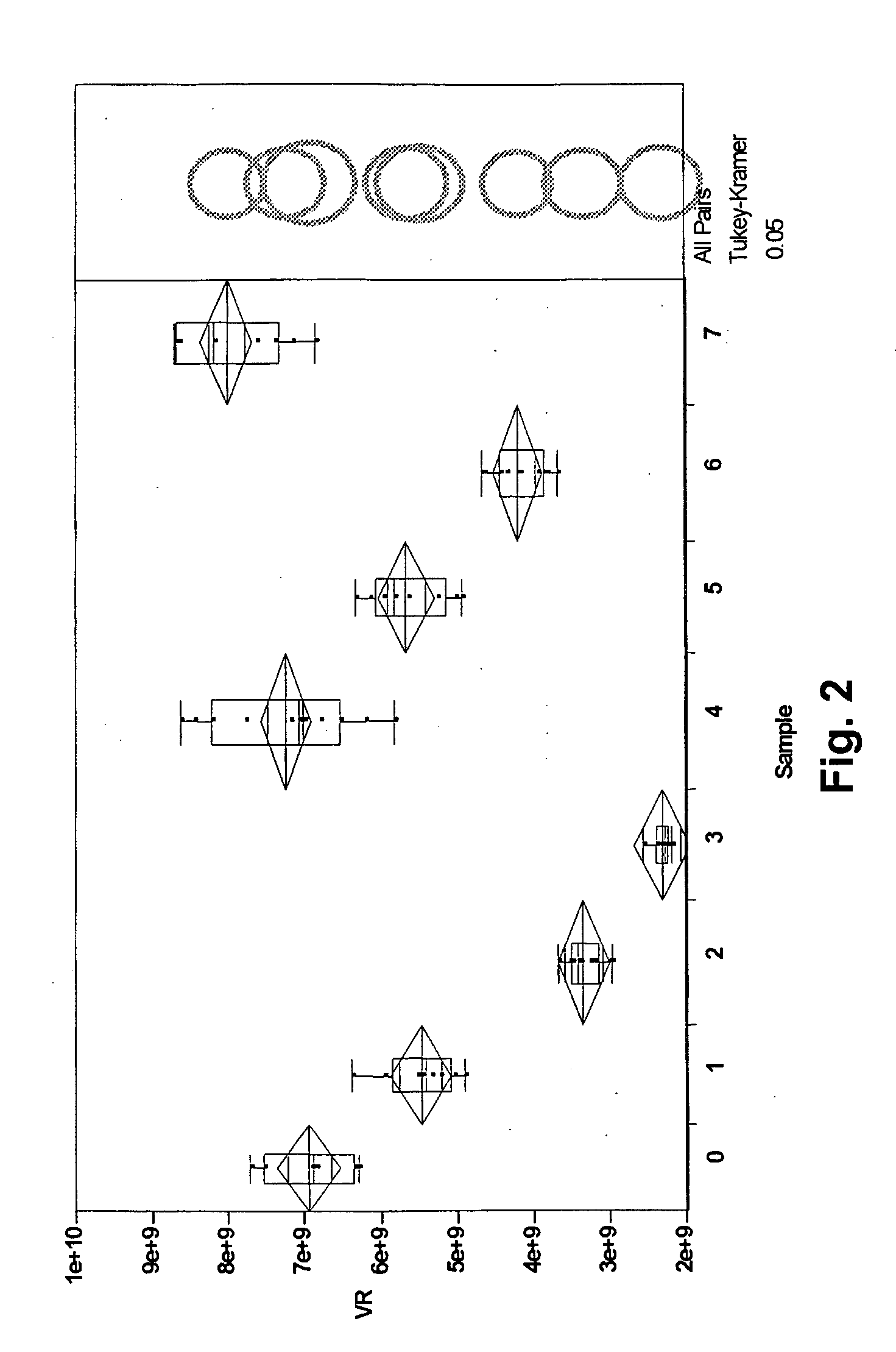
[0075] A base adhesive material was prepared by blending NeoRez (Registered Trade Mark) 9630 and NeoRez 9330, two polyurethane dispersions available commercially from NeoResins, Inc., 730 Main Street, Wilmington Mass. 01887. This material was divided into eight samples of approximately 50 g each, each sample containing 40 percent by weight of solids, and varying amounts of potassium acetate, tetrabutylammonium chloride, or poly(acrylic acid) aqueous solution were added as indicated in the Table below; a control sample was also provided with no additives.

TABLESampleWeight ofMass (g) ofNo.sample (g)Additiveadditive050.12N / A0150.00Bu4NCl0.012250.06Bu4NCl0.051350.30Bu4NCl0.099450.10KOAc0.007549.99KOAc0.040650.00KOAc0.082750.00PAA, sodium salt0.156(40% wt aq.)

[0076] Each of the samples was mixed for a period of 7 to 10 days to ensure a thoroughly homogeneous product and to re-disperse any gel-like solids, which formed as a result of adding the additive as a solid to the sample. At the ...

example 2

[0079] This Example illustrates the effect of tetrabutylammonium hexafluorophosphate (NBU4PF6) in lowering the volume resistivity of an adhesive material as described in the aforementioned copending application Ser. No. 10 / 715,916.

[0080] Stock solutions of NBu4PF6 containing from 10 to 200 mg of the salt per gram of solution were prepared, and added to various aliquots of a polyurethane dispersion to produce the desired levels of the salt ranging from 10−7 to 10−4 moles of the salt per gram of adhesive solids (approximately 100 to 100,000 ppm of the salt on a weight / weight adhesive solids basis). The resultant salt solution / dispersion mixtures were mixed on a roller mill for at least three hours to ensure complete mixing.

[0081] The salt-containing dispersions thus prepared were coated in the same way as in Example 1 above and dried at 60° C. in air for at least 10 minutes to produce dried adhesive layers having thicknesses from 12 to 20 μm. The resultant adhesive layers were then ...


PUM

PropertyMeasurementUnit
temperaturesaaaaaaaaaa
resistivitiesaaaaaaaaaa
temperatureaaaaaaaaaa

Abstract

An electro-optic display comprises first and second substrates, and an adhesive layer and a layer of electro-optic material disposed between these substrates, the adhesive layer comprising a mixture of a polymeric adhesive material and an additive selected from a salt, a polyelectrolyte, a polymer electrolyte, a solid electrolyte, a conductive metal powder, a ferrofluid, a non-reactive solvent, a conductive organic compound, and combinations thereof. In one aspect, there is provided an adhesive comprising a mixture of a polymeric adhesive material and an additive selected from a salt, a polyelectrolyte, a polymer electrolyte, a solid electrolyte, and combinations thereof.

Description

CROSS-REFERENCE TO RELATED APPLICATIONS [0001] This application is a divisional of application Ser. No. 10 / 810,761, filed 26 Mar. 2004, which claims the benefit of Provisional Application Ser. No. 60 / 320,059, filed Mar. 27, 2003, both of which are incorporated herein by reference in their entirity. [0002] This application is also related to (a) copending application Ser. No. 10 / 064,389, filed Jul. 9, 2002 (Publication No.2003 / 0025855), which itself claims benefit of Provisional Application Ser. No. 60 / 304,117, filed Jul. 9, 2001; (b) copending application Ser. No. 10 / 249,957, filed May 22, 2003 (Publication No. 2004 / 0027326), which itself claims benefit of Provisional Application Ser. No. 60 / 319,300, filed Jun. 10, 2002, and Provisional Application Ser. No. 60 / 320,186, filed May 12, 2003; and (c) copending application Ser. No. 10 / 605,024, filed Sep. 2, 2003, which itself claims benefit of Provisional Application Ser. No. 60 / 319,516, filed Sep. 2, 2002. [0003] The entire contents of ...

Claims


Application Information

Patent Timeline
Patent Type & Authority Applications(United States)
IPC IPC(8): B32B7/06B32B7/12C09J9/02C09J11/02G02F1/167G02F1/1675
CPCB32B7/06B32B7/12G02F2202/28C09J11/02G02F1/167C09J9/02G02F1/1675
Inventor KLINGENBERG, ERIC HOWARDFAZEL, SHAFIQ NISARALIHONEYMAN, CHARLES H.
Owner VERSUM MATERIALS US LLC
Learn More