
Stent for intracranial vascular therapy and process for producing the same

a technology stents, which is applied in the field of stents used for intracranial vascular therapy, can solve the problems of significant reduction of patient load, low radial force of coil stents, and a small radial force disadvantage, so as to achieve safe holding, no biological reaction, and elevated visibility

Inactive Publication Date: 2005-06-09
KANEKA CORP
View PDF4 Cites 13 Cited by
  • Summary
  • Abstract
  • Description
  • Claims
  • Application Information

AI Technical Summary

Benefits of technology

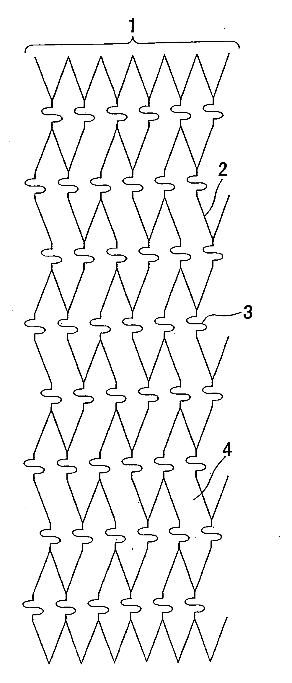
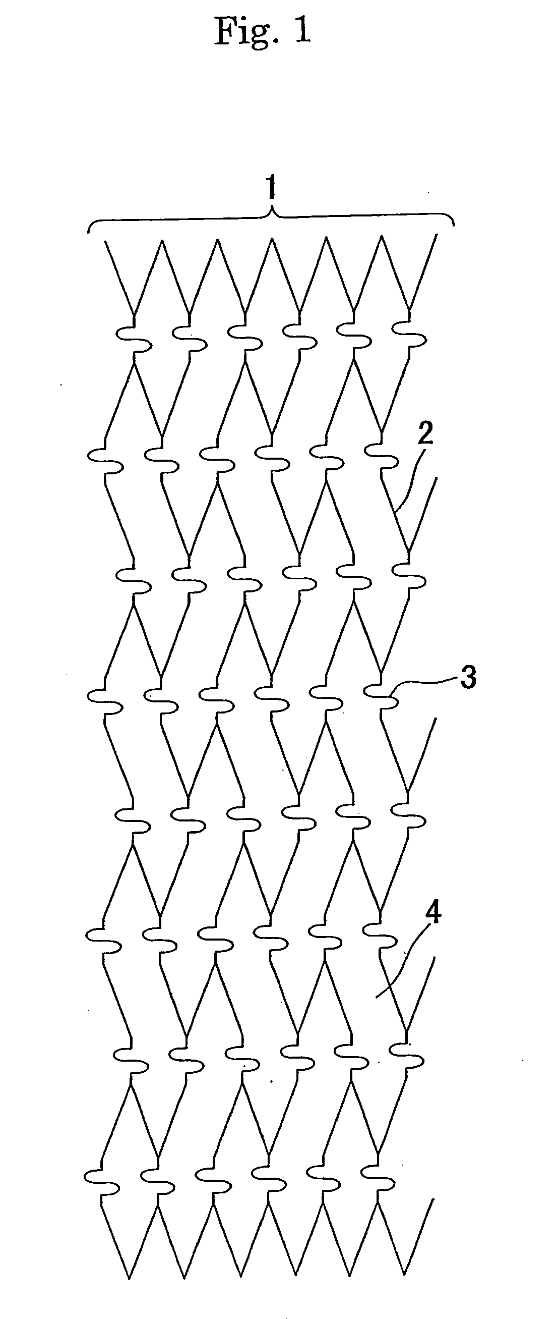
[0023] Accordingly, in consideration of the above-described problems, an object of the present invention is to provide a stent for intracranial vascular therapy and a process for producing the same which has flexibility for allowing the stent to be safely held in the intracranial arteries, induces no biological reaction in the blood vessels due to galvanic corrosion or the like, and has elevated visibility under X-ray radioscopy.

Problems solved by technology

Also, the percutaneous therapy requires a short time for the therapy and significantly decreases a load on a patient.
However, dilation therapy of a stenosed region of the cardiac coronary arteries using a balloon catheter has the large problem of causing restenosis in about 40% of patients after the passage of about 3 months to 6 months from the therapy.
However, the coil stent has the disadvantage of slightly low radial force.
Although the slotted tube stent has the advantage of high radial force, it has the disadvantage that it has relatively low flexibility and easily causes obstruction in the side branches.
However, it is pointed that coil embolization therapy of intracranial aneurysms has the large problem of limiting applicable cases.
Namely, it is pointed out that there is the danger that a coil held in an aneurysm such as a wide neck aneurysm or a fusiform aneurysm having a large width at its root easily migrates to the parent blood vessel, and a thrombus formed in the migrating coil is dispersed by the bloodstream to cause cerebral infarction.
First, it is difficult to safely hold a stent for the cardiac coronary arteries in the intracranial arteries.
A conceivable main cause of difficulty in safely holding a stent for the cardiac coronary arteries is that the stent for the cardiac coronary arteries cannot track the anatomically complicated tortuousness of the intracranial arteries.
Second, the stent for the cardiac coronary arteries held in the intracranial arteries has low visibility under X-ray radioscopy.
Low visibility causes difficulty in precisely holding the stent in a target site and difficulty in obtaining information of the properties of the held stent in each diagnosis after the operation, thereby causing difficulty in obtaining a sufficient therapeutic effect.
As disclosed in the above publication, when the sheet stent which becomes imperforate is held in the blood vessels, the thrombus formed around the stent may propagate downward in the blood vessels to cause the danger of acute obstruction.
Therefore, as disclosed in the prior art, when the sheet stent composed of a metal material is covered with a different metal or provided with a marker composed of a different metal for increasing visibility under X-ray radioscopy, galvanic corrosion occurs, and thus inflammatory response quite possibly occurs in the blood vessels.
Although the inflammatory response is known to cause vascular obstruction, restenosis, or the like, the prior art has no consideration of this point.

Method used


Image

  • Stent for intracranial vascular therapy and process for producing the same
  • Stent for intracranial vascular therapy and process for producing the same
  • Stent for intracranial vascular therapy and process for producing the same

Examples


example 1

[0058] (Step a) A slotted tube stent (diameter after expansion: 3.0 mm, length: 18 mm, the number of links in the stent length direction: 6, and the number of links in the stent circumferential direction: 6) was produced by laser-cutting stainless steel SUS316L and used as a cathode, and platinum-plated titanium was used as an anode for electrolytic plating in an acid copper plating bath at 25° C. (200 g / l of copper sulfate and 50 g / l of sulfuric acid) under stirring with a magnetic stirrer with a current density of 7.8 A / dm2 for 30 minutes to form copper layers to a thickness of about 10 μm on the outer surface, the inner surface and the sides of the slotted tube stent. After electrolytic plating, the stent was washed in distilled water and then dried.

[0059] (Step b) The slotted tube stent having the copper layers having a thickness of about 10 μm was placed on the outer surface of a single lumen tube (inner diameter 0.53 mm, outer diameter 1.55 mm) which was produced by extrusion...

example 2

[0063] Five stents were produced by the same method as in Example 1 except that in the step c, electrolytic plating of gold was performed for 90 minutes to form gold layers of about 100 μm in thickness.

example 3

[0064] Five stents were produced by the same method as in Example 1 except that in the step c, electrolytic plating was performed in a platinum plating bath at 80° C. (Platanex 3LS produced by Electroplating Engineers of Japan Ltd.) under stirring with a magnetic stirrer with a current density of 2.0 A / dm2 for 300 minutes to form platinum layers of about 60 μm in thickness on the outer surfaces of the stents.


PUM


Abstract

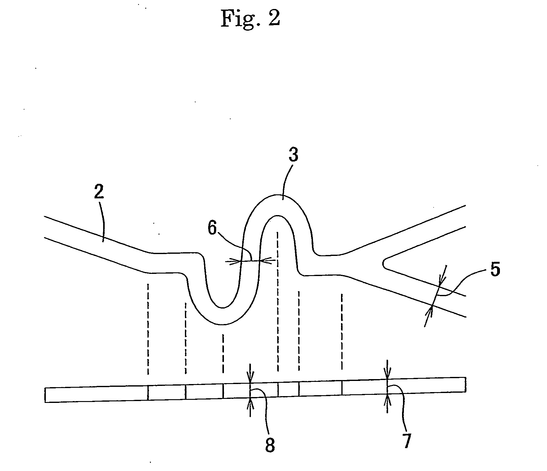
The present invention provides a stent for intracranial vascular therapy which can be safely held in the intracranial arteries, induces no biological reaction in the blood vessels due to galvanic corrosion or the like, and has elevated visibility under X-ray radioscopy. A stent of the present invention includes a plurality of main struts and a plurality of link struts as its constituents, wherein the stent is made of a single material having higher radiopacity than that of stainless steel, and the main struts and the link struts each have a width ranging from 100 μm to 200 μm and a thickness ranging from 50 μm to 100 μm.

Description

TECHNICAL FIELD [0001] The present invention relates to a stent used for intracranial vascular therapy, and more specifically to a stent used for dilation therapy of a stenosed region formed in the intracranial blood vessels, and for coil embolization therapy of an aneurysm formed in the intracranial blood vessels. BACKGROUND ART [0002] There is an increasing tendency to relieve a patient's pain and load in a surgical operation and to give importance to quality of life (QOL). Also, in combination with the progress of the aging of society, a conventional indiscriminate standard surgical operation has been converted to a reduced surgical operation, and percutaneous less-invasive therapy such as an endoscopic operation or the like has been regarded as important, thereby making wide use of some percutaneous therapies. [0003] An example of therapies for angina pectoris and myocardial infarction derived from arteriosclerosis or the like is percutaneous angioplasty in which a stenosed regi...

Claims


Application Information

Patent Timeline
IPC IPC(8): A61F2/00A61F2/915A61L31/00A61M29/02
CPCA61F2/91A61F2/915A61F2002/91525A61F2250/0098A61F2002/9155A61F2002/91558A61F2002/91541A61F2/07A61F2/06A61L27/04A61M29/02
Inventor IWATA, HIROONISHIDE, TAKUJI
Owner KANEKA CORP
Learn More