Directional spatial video noise reduction

a spatial video and noise reduction technology, applied in the field of video signal processing, can solve the problems of increasing compression, noise may significantly reduce the effectiveness of compression schemes, and certain features of images, such as object edges, can look a lot like noise, so as to improve the quality of compressed video, reduce computational burden, and simple implementation

Inactive Publication Date: 2005-06-23
GOOGLE TECH HLDG LLC
View PDF36 Cites 119 Cited by
  • Summary
  • Abstract
  • Description
  • Claims
  • Application Information

AI Technical Summary

Benefits of technology

[0061] A first filtering technique is described for spatial noise reduction in video images. The first technique provides directional video filtering for locally adaptive spatial noise reduction having the aforementioned and other advantages. The first technique can be implemented as a pre-processing filter to improve the quality of compressed video, such as MPEG-1, MPEG-2, or MPEG-4 video, including compressed video for broadcast or multi-media streaming. The first technique extends directional low pass filtering for pre-processing video sequences prior to compression by providing both parametric adjustment of degree of smoothing and reduced computational burden for simple implementation.

Problems solved by technology

A problem which is pervasive to noise filtering is that certain features of images, such as object edges, can look a lot like noise when filtering is performed on a pixel-by-pixel basis.
Noise reduction is important in connection with compression of image information, because noise may significantly reduce the effectiveness of compression schemes, particularly frequency-domain compression schemes such as the various MPEG video standards.
In image compression technology there is typically a trade-off between compression and image quality; increased compression may tend to reduce image quality.
It is not always easy to reconcile these differences so as to achieve high quality highly compressed images.
Once the noise is present in the signal it is very difficult to remove.
Historically, techniques such as high-frequency roll-off have been employed, frequently doing more damage to the underlying pictures than the noise itself.
As discussed in the '578 Patent, in the art of image processing, raw images of an object / scene captured from a sensing or capture device are often subject to varying types of “noise” (elements not present in the object or environment which may nonetheless appear in the image).
The noise present in an image may be due to the characteristics of the imaging system such as the sensor or processing steps subsequent to the initial image capture which may add noise while trying to achieve a different purpose.
The properties and characteristics that would indicate that a pixel or region of pixels is “noisy” and the properties that would indicate a pixel or region of pixels is an edge or a fine detail of the image are difficult to distinguish.
Thus, a fundamental problem with the removal of noise is that often a removal of what is indicated as noise may actually be a removal of fine edge or detail.
While median hybrid has been shown to work quite well in discriminating some edges, it is deficient in several respects with regard to edge detection.
For instance, an edge feature may lie at a 33 degree vector from a particular pixel, and thus the eight directions are inadequate in determining the edge feature.
When applied to digital images, the median hybrid filter, if applied everywhere to all pixels, may propagate noise or shift it from pixel to pixel while attempting to remove it since there is noise along the edge feature due to the non-cardinal direction of the edge.
Median filters often introduce additional artifacts which corrupt edges in the image.
However, in video signal processing, these “invisible” artifacts can be detrimental to other objectives, such as achieving a high compression ratio for storage and transmission of the video image.
First, Wiener filters remove noise that is not very visible to the eye, such as noise related to film grain.
As such, the desired video quality is less than optimal.
Although much of this noise is often biased towards the high frequency parts of the spectrum and is not particularly visible in an analog system, MPEG encoding of such material often introduces Discrete Cosine Transform (DCT) effects or artifacts that “crawl” around the picture.
First, the presence of noise causes many small amplitude high frequency DCT coefficients to be generated and sent in the bit stream.
These coefficients tend to be more inaccurately quantized than the low frequency coefficients and are generally due to the noise only.
The net result is that the whole picture is reduced in quality.
The Forward Prediction (P) and Bi-directional prediction (B) frames that follow the Intra (I) frame try to constantly correct for the noise in the prediction path and so this results in the DCT artifacts changing from frame to frame.
This produces even worse predictions in the ‘B’, and ‘P’ frames which inevitably increases the QP and reduces picture quality.
The image can be corrupted by noise in different ways.
Some noise sources are located in a camera and become active during image acquisition especially under bad lighting conditions.
Further noise is added by image recording devices such as VCRs.
In these devices, additive white Gaussian noise or, in the case of tape drop-outs, impulsive noise is added to the signal.
Jostschulte aptly notes that the problem of a spatial noise reduction scheme is to eliminate spatially uncorrelated noise from spatially correlated image content.
As noted in Jostschulte, the disadvantage of such a system is the tendency to blur edges and lines of the image.
Jostschulte mentions that several algorithms for precise detection of edge-directions are known, but that nearly all of them have in common that a hardware implementation will be very expensive.
According to Jostschulte, if this were not the case, sharpness in object-comers could be lost.
Locally adaptable directional low pass filtering as described in Jostschulte minimizes edge blurring, but provides no means to adjust the degree of smoothing for optimized quality at a given bit rate.

Method used


Image

  • Directional spatial video noise reduction
  • Directional spatial video noise reduction
  • Directional spatial video noise reduction

Examples


Embodiment Construction

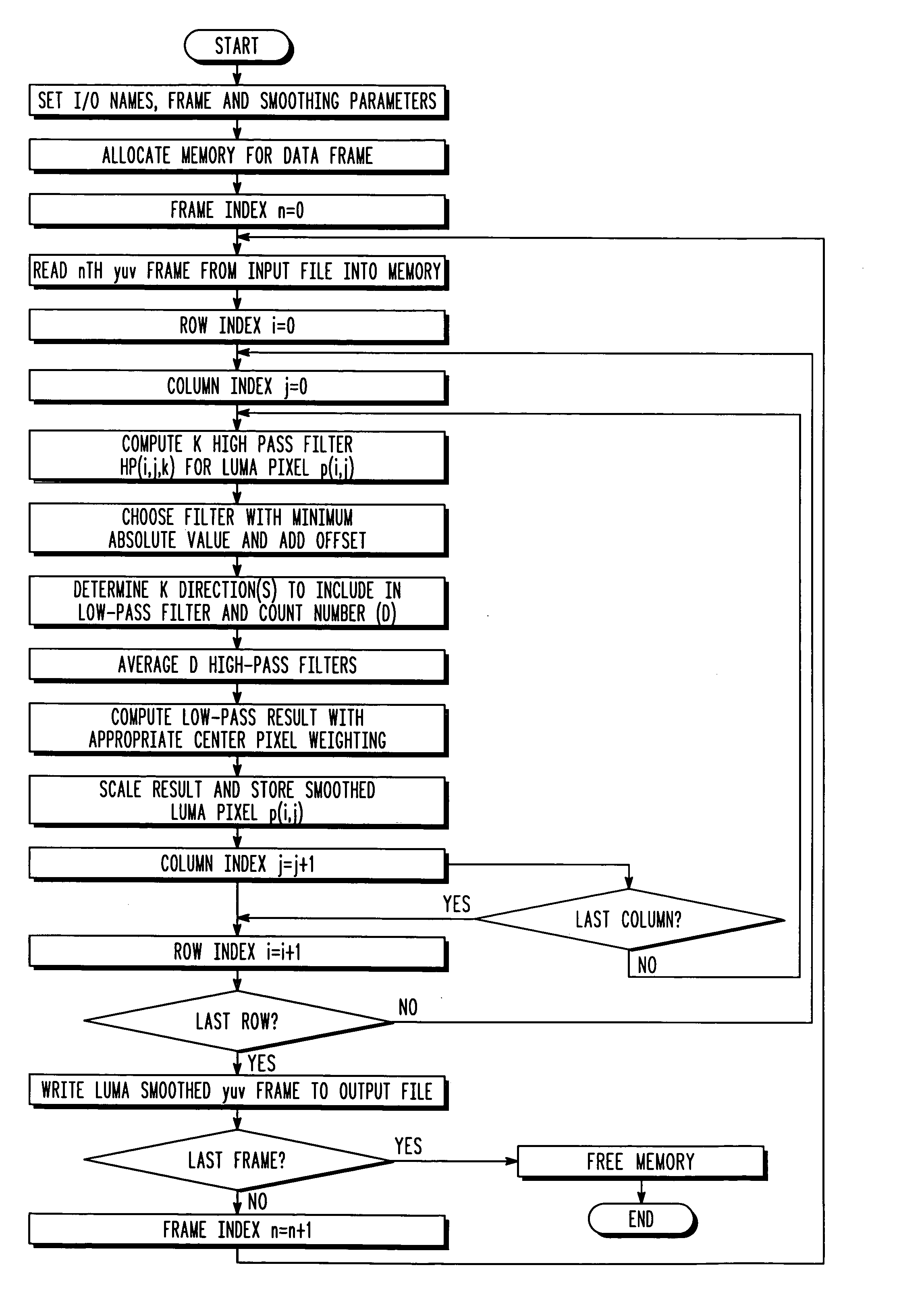
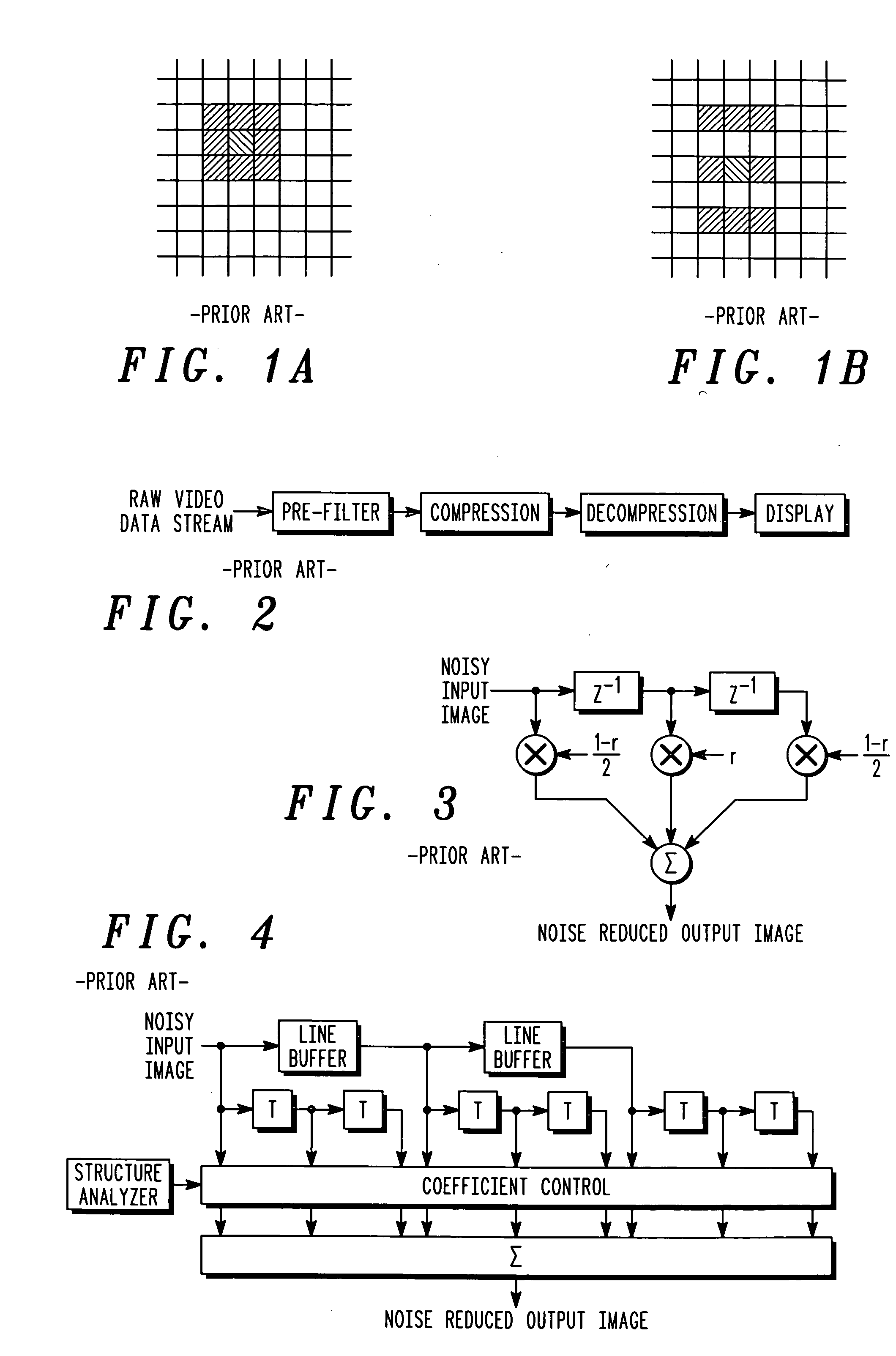
[0117] The invention relates generally to directional adaptive filters for spatial noise reduction pre-processing in conjunction with video compression. More specifically, the directionally adaptive spatial smoothing filters described herein are based upon applying low pass filtering only along object boundaries and unstructured areas so as to minimize the tendency to blur image edges.

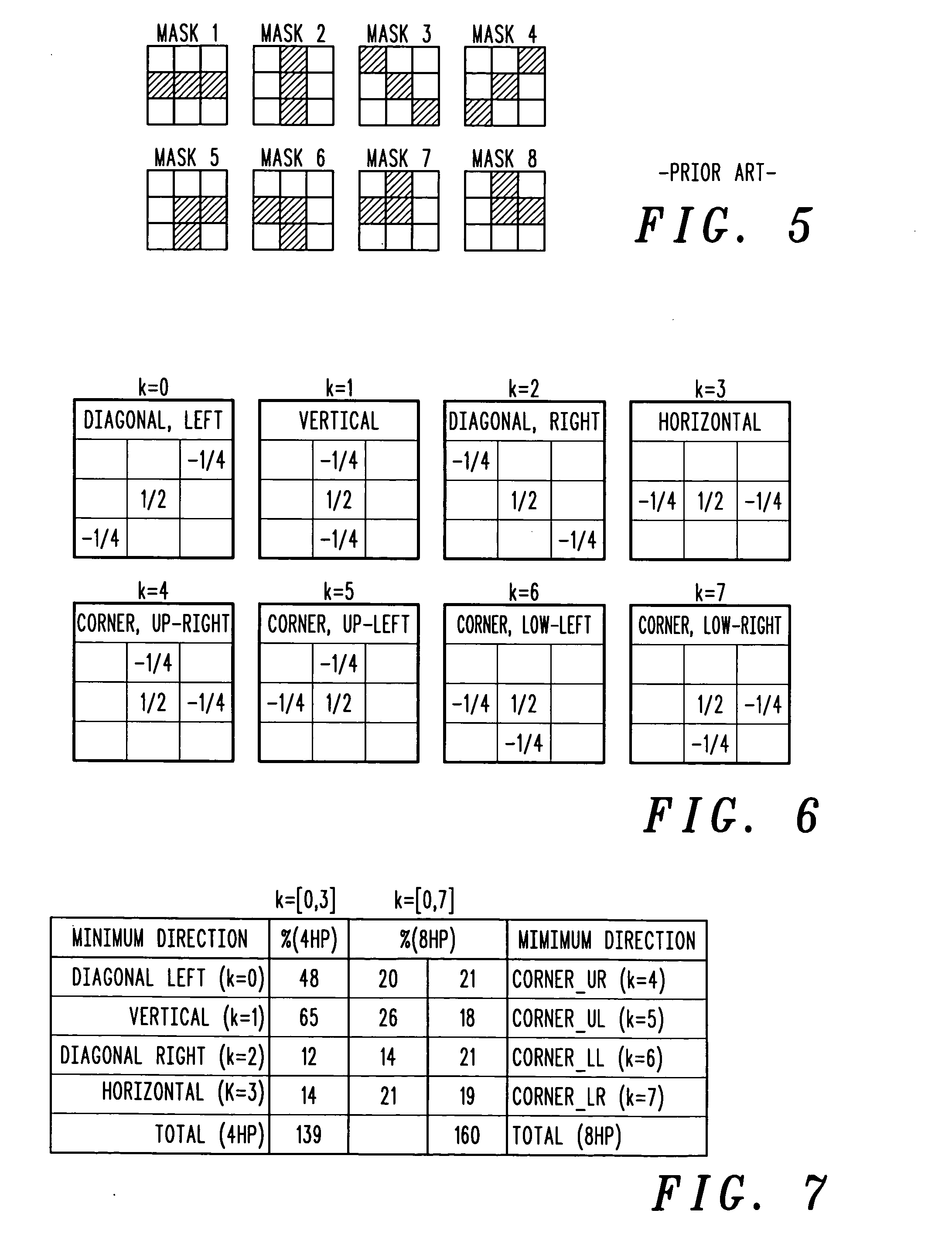
[0118] Local edge detection for each pixel in an image may be accomplished by applying 3-tap high pass filters in eight directions to determine the best direction for local low pass filtering, such as has been described in “Perception Adaptive Temporal TV-Noise Reduction Using Contour Preserving Prefilter Techniques”, Jostschulte, K., Amer, A., Schu, M., Schroeder, H., IEEE Trans. of Consumer Electronics, Vol. 44, No. 3, pp. 1091-1096 (“Jostschulte”). Jostschulte has been discussed, hereinabove.

[0119] Several enhancements to the basic directional low pass filtering algorithm as presented in Jostschul...


PUM


Abstract

A method of reducing spatial noise in an image. Low-pass (smoothing) filters are calculated simultaneously from three successive image rows. Three blocks (m1, m2, m3) are associated with the three successive image rows, and the blocks are processed in row-major order. This implementation is applicable to both luminance and chrominance. The number of smoothing parameters is reduced to one. The technique is applicable to both luminance and chrominance. Directional mapping is used. Extension of the technique to spatial filtering using a 5×5 neighborhood (using five successive image rows) is described. Embodiments of the method using the MMX instruction set are described.

Description

CROSS-REFERENCE TO RELATED APPLICATIONS [0001] This is a continuation-in-part of commonly assigned U.S. patent application Ser. No. 10 / 744,721, filed on Dec. 23, 2003 and incorporated herein by reference.FIELD OF THE INVENTION [0002] The present invention relates to video signal processing and, more particularly, to digital filtering techniques for noise elimination. BACKGROUND [0003] A sequence of still images creates the illusion of motion. In film (motion pictures), there are normally 24 frames per second. To create the illusion of motion, the image in each frame varies slightly from the image in the preceding frame. (At scene cuts, there are large, abrupt changes in the image.) In video, there are typically 30 frames per second. A video image comprises hundreds of scan lines. In interleaved video, each frame comprises two fields. Each field image contains half of the scan lines (odd or even), and can be thought of as being a half-resolution frame image. [0004] The present invent...

Claims


Application Information

Patent Timeline
Patent Type & Authority Applications(United States)
IPC IPC(8): G06K9/00G06K9/40G06T5/00
CPCG06T5/002H04N5/213G06T2207/20012G06T2207/10016
Inventor ANDERSON, CANDACE M.
Owner GOOGLE TECH HLDG LLC
Why Eureka
Try Eureka