Signal processing circuit and quadrature demodulation apparatus and method of estimating error thereof

a signal processing circuit and quadrature demodulation technology, applied in the direction of amplitude demodulation, orthogonal multiplex, phase-modulated carrier system, etc., can solve the problem that the amplitude error (i.e., the gain difference) of the i/q signal will be placed under influence, and cannot always have a property of uniform distribution, etc., to achieve high speed, improve the bit error rate characteristic, and estimate accurately

Inactive Publication Date: 2005-07-07
FUJITSU LTD
View PDF7 Cites 38 Cited by
  • Summary
  • Abstract
  • Description
  • Claims
  • Application Information

AI Technical Summary

Benefits of technology

[0033] The present invention is made in view of the above aspect. Therefore, it is an object of the present invention to provide a signal processing circuit, a quadrature demodulation apparatus and a method of estimating error therefor in which it becomes possible to accurately estimate not only amplitude error but also phase error caused in a signal inherent to characteristics of devices such as those constituting a quadrature demodulation unit or the like of a receiver, to correct the estimated error component at a high rate without introducing any feedback control, and to eliminate deterioration in the signal quality.
[0051] As described above, according to the present invention, owing to the cross-correlation value calculating unit and the phase error calculating unit of the phase error detecting unit, even if the components constituting the receiver have inherent characteristics, i.e., these device characteristics of the components constituting the receiver cause the phase error between the I-component and the Q-component, it becomes possible to carry out accurate estimation on the phase error by additionally providing the signal processing circuit function with a simple arrangement at a stage for carrying out the baseband processing. Therefore, signal deterioration can be eliminated by correcting the phase error, and the S / N ratio and the bit error rate can be improved.
[0052] In particular, if signal transmission is requested for a signal necessitating a relatively high S / N ratio such as one using a multi-code in a spread spectrum demodulation or one using a multi-value demodulation, the requested level of S / N ratio can be secured.
[0053] Further, when the phase error correction is carried out, the correction can be achieved without providing a feedback control. Therefore, the phase error can be accurately estimated as described above, and the circuit for carrying out the phase error correction comes to have a high response speed.
[0055] As described above, according to the present invention, since the phase error detecting unit is provided in each of the signal processing circuit modules, in addition to the advantages similar to those of the aforesaid case, the phase error detection on the OFDM signal in particular can be carried out for each of the subcarriers independently. That is, as for the OFDM signal, it is assumed that the phase error between the I-component and the Q-component can be caused in a different manner depending on each subcarrier by the characteristics inherent to the components constituting the receiver. However, if some simple signal processing circuit function is added to a stage for carrying out the baseband processing, then the phase error caused depending on each subcarrier can be estimated accurately and at a high speed. Accordingly, the S / N ratio and the bit error rate characteristic can be remarkably improved.
[0056] Furthermore, the control unit can function as a unit for controlling the amplitude error detecting unit and the phase error detecting unit so that when the test mode is selected the amplitude error and the phase error detected by the amplitude error detecting unit and the phase error detecting unit are stored in the amplitude error holding unit and the phase error holding unit, respectively. Also, the control unit can function as a unit for controlling the amplitude error correcting unit and the phase error correcting unit so that when the practical mode is selected the amplitude error correcting unit and the phase error correcting unit effect the amplitude error correction and the phase error correction on the couple of signals driving from the quadrature demodulation in the quadrature demodulation unit based on the contents stored in the amplitude error holding unit and the phase error holding unit, respectively. Therefore, when the mode selection is made to take place the practical mode in which the receiving processing is effected on the signal transmitted through the actual radio wave transmission channel, this receiving processing can be carried out in a simple manner by the signal processing circuit module provided for each subcarrier, with the result that processing load imposed on the overall arrangement of the apparatus can be decreased.

Problems solved by technology

For this reason, amplitude error tends to occur between the I-signal and the Q-signal.
As a consequence, the amplitude error (i.e., the gain difference) of the I / Q signals will be placed under influence of the amplitude error of the I-side signal.
Furthermore, one of device components arranged as the zero-degree hybrid 104a and the ninety-degree hybrid 104c cannot always have a property of uniform distribution of a signal having an ideal angle relative to the input, due to the inherent device characteristic.
Therefore, for example, the high frequency component tends to have error proceeding relative to the zero-phase in the radio frequency signal band, and the low frequency component tends to have error delaying relative to the zero-phase.
These components have variation in gain and this variation causes an electric power value difference in the I / Q signals and this electric power value difference will also cause amplitude error.
If the received signal component containing the above-described received amplitude error and the phase error (such kind of errors will sometimes take amplitude-phase error as a generic name) is subjected to data demodulation processing in the digital demodulation processing unit 107, then difficulty will be brought about in improvement of the BER (bit error rate) characteristic.
However, if the receiver 100 is requested to handle a signal in a manner of spread spectrum coding or to transmit a signal having a format necessitating a high S / N ratio such as of multilevel coding signal, the amplitude-phase error components will look like a noise, with the result that relatively large influence will be caused on the BER ratio.
However, according to the technology disclosed in the above-introduced Patent Document 1, the signal processing thereof will suffer from influence caused by phase error until the error correction processing comes to have stable accuracy and the feedback control goes into a stable operation mode.
For this reason, it is difficult for the received signal to be subjected to phase error correction and amplitude error correction for a certain period of time in which the feedback control goes into a stable operation mode.
Therefore, when more improvement is tried in bit error rate, the technology will encounter certain difficulties.
Furthermore, since the technology includes a feedback control, it is difficult for the received signal to be subjected to amplitude error correction for a certain period of time in which the feedback control goes into the stable operation mode.
Therefore, even if the amplitude error correction and the phase error correction are effected on the I-signal and the Q-signal which are obtained by the quadrature demodulation processing, the I-signals and the Q-signals of respective subcarriers will not effectively undergo the amplitude error correction and the phase error correction, with the result that the characteristic of the received signal is not satisfactorily improved.

Method used


Image

  • Signal processing circuit and quadrature demodulation apparatus and method of estimating error thereof
  • Signal processing circuit and quadrature demodulation apparatus and method of estimating error thereof
  • Signal processing circuit and quadrature demodulation apparatus and method of estimating error thereof

Examples


first embodiment

[a] Description of First Embodiment

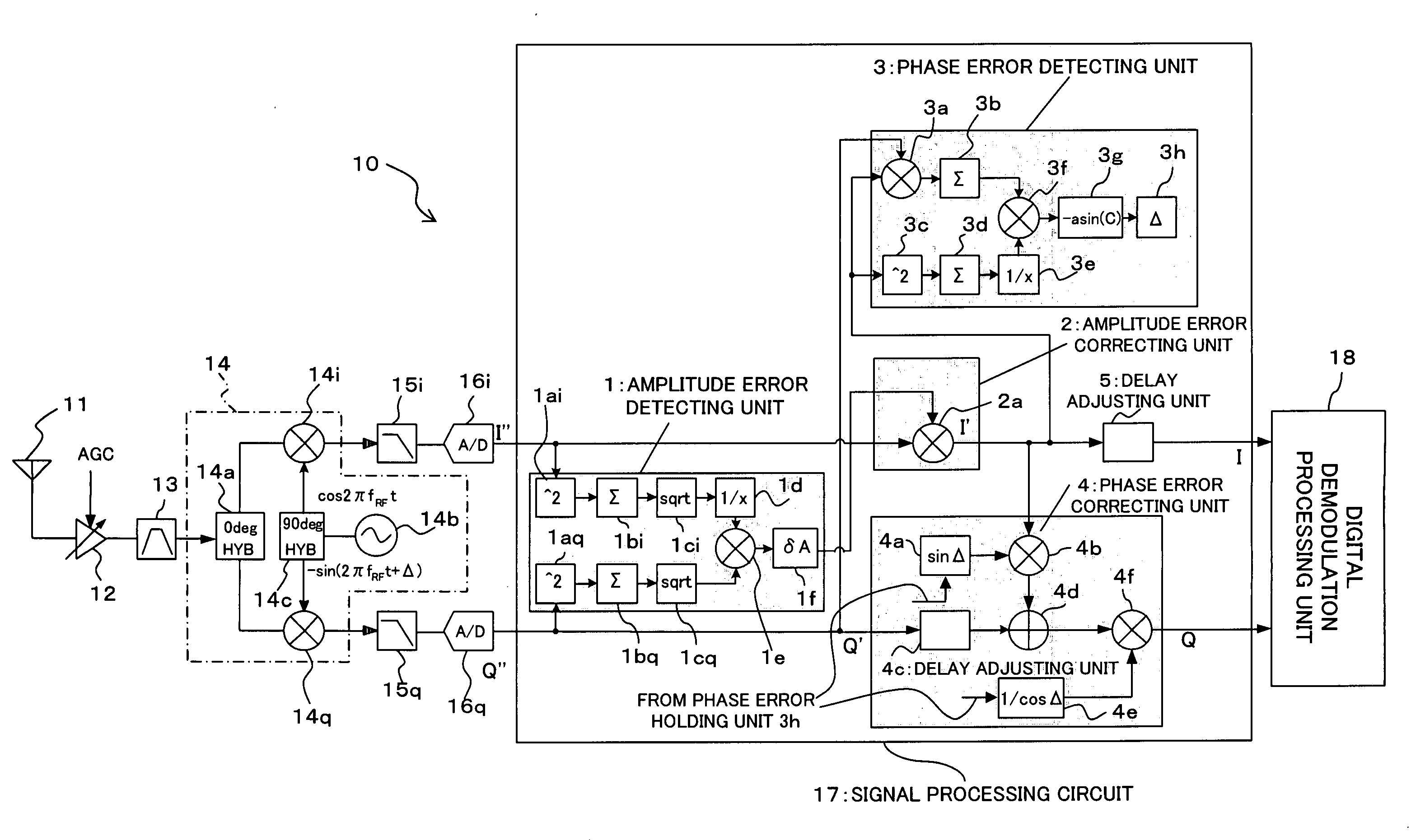
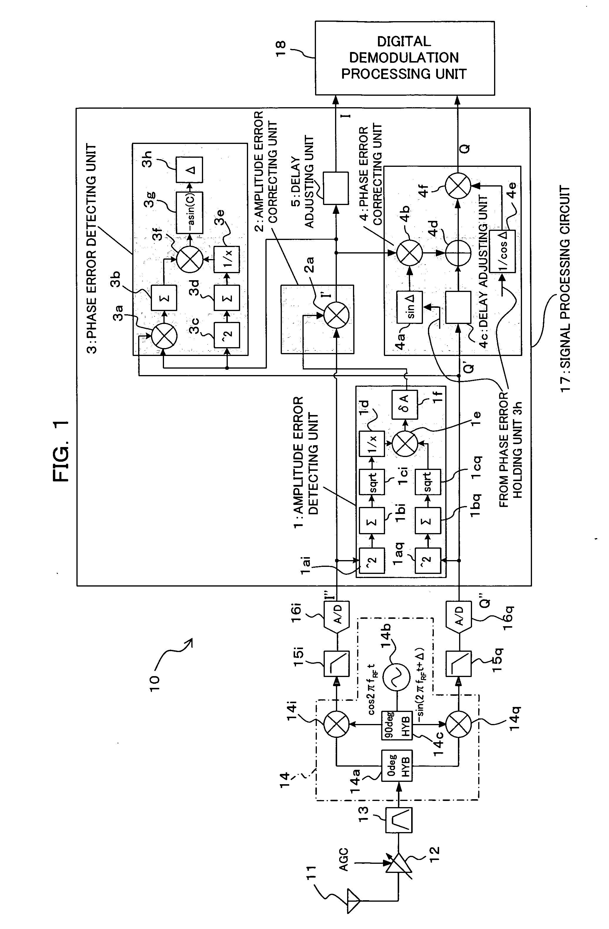
[0070]FIG. 1 is a block diagram showing a receiver 10 of a first embodiment according to the present invention. The receiver 10 shown in FIG. 1 is capable of receiving a signal transmitted from a transmitter not shown, for example. When the transmitter transmits a data signal, the transmitter effects quadrature demodulation on the data signal so that the signal is sent as a radio wave frequency signal. As will be described later on, the receiver 10 shown in FIG. 10 has an arrangement with a feature of the present invention which can effect estimation and correction on amplitude error and phase error which can be brought about due to the inherent characteristics of devices for data demodulation processing in the prior processing stage.

[0071] As shown in FIG. 1, the receiver 10 has an antenna 11, an AGC amplifier 12, a band-pass filter 13, a quadrature detection unit 14, low-pass filters 105i and 105q, A / D converters 16i and 16q and a digital demodu...

second embodiment

[b] Explanation of Second Embodiment

[0125]FIG. 4 is a block diagram showing an arrangement of a receiver 40 according to a second embodiment of the present invention. Also in the receiver 40 shown in FIG. 4, a radio wave transmission signal transmitted from a transmitter not shown, for example, is received. The above arrangement is different from that of the aforesaid first embodiment in the following points. That is, the receiver 40 shown in FIG. 4 is arranged to receive an OFDM signal as a signal from an apparatus on the transmission side, and the amplitude error correction, the phase error correction and the demodulation are made on the OFDM received signal.

[0126] To this end, the receiver 40 of the second embodiment comprises the antenna, the AGC amplifier 12, the band-pass filter 13, the quadrature detection unit 14, the low-pass filters 15i and 15q, and the A / D converters 16i and 16q, which have the similar functions to those of the receiver 10 of the aforesaid first embodime...

third embodiment

[c] Explanation of Third Embodiment

[0142]FIG. 6 is a block diagram showing a receiver 50 according to a third embodiment of the present invention. The arrangement of the receiver 50 shown in FIG. 6 is the same as the aforesaid second embodiment in that the amplitude error correction and the phase error correction are effected on the OFDM received signal and demodulation is also effected on the OFDM received signal. However, the arrangement of the receiver 50 shown in FIG. 6 is different from that of the aforesaid second embodiment in that the arrangement thereof is additionally provided with a switching mechanism which makes it possible to carry out operation mode switching action between a test mode and a practical mode.

[0143] To this end, the receiver 50 of the third embodiment comprises a changeover switch 51 between the antenna 11 and the AGC amplifier 12, a signal processing circuit 52 different from that of the second embodiment, and a controller 53 for controlling the switch...


PUM


Abstract

To provide a signal processing circuit which makes it possible to accurately estimate not only amplitude error but also phase error of a signal caused by device characteristics of components of a receiver, correct swiftly the error component without providing feedback control, and eliminate signal deterioration. This signal processing circuit is arranged to have a cross-correlation value calculating unit for calculating a cross-correlation value of a pair of signals having undergone a quadrature detection and a phase error calculating unit for calculating a phase displacement of one of the pair of signals with respect to the other of the same as a phase error based on the cross-correlation value calculated by the cross-correlation value calculating unit.

Description

BACKGROUND OF THE INVENTION [0001] 1) Field of the Invention [0002] The present invention relates to a signal processing circuit for carrying out signal processing on an I (In-Phase) signal and a Q (Quadrature) signal having undergone quadrature detection and a quadrature demodulation apparatus and a method of estimating the error thereof which are suitable for use in a receiver of a communication system, or more preferably in a receiver of a radio wave communication system. [0003] 2) Description of the Related Art [0004]FIG. 8 is a block diagram showing a general arrangement of a receiver 100. As shown in FIG. 8, the receiver 100 has an antenna 101 and a radio wave signal sent from a transmitter not shown can be received by the antenna 101. The signal received by the antenna 101 is placed under control of an AGC (Automatic Gain Control) amplifier 102 so that the signal has a constant gain. This signal is supplied to a band-pass filter 103 in which unnecessary wave components are re...

Claims


Application Information

Patent Timeline
Patent Type & Authority Applications(United States)
IPC IPC(8): H04L27/38H04J11/00H04L27/00H04L27/06H04L27/22H04L27/26
CPCH04L27/0014H04L27/2647H04L2027/0067H04L2027/003H04L2027/0016
Inventor NISHIKAWA, TAKUROU
Owner FUJITSU LTD
Why Eureka
Try Eureka