Method of catastrophic transfer of a thin film after co-implantation

a technology of co-implantation and thin film, which is applied in the direction of basic electric elements, semiconductor/solid-state device manufacturing, electric devices, etc., can solve the problems of affecting the crystalline reducing the quality of the material, and reducing the possibility of crystalline defects during the following treatment, so as to achieve high mechanical stress, low roughness of the surface, and high quality

Active Publication Date: 2005-07-07
COMMISSARIAT A LENERGIE ATOMIQUE ET AUX ENERGIES ALTERNATIVES +1
View PDF58 Cites 57 Cited by
  • Summary
  • Abstract
  • Description
  • Claims
  • Application Information

AI Technical Summary

Benefits of technology

[0014] The present invention relates to a method of transferring a thin layer leading to low roughness of the surface of the transferred layer, and not involving high mechanical stresses in case of materials having high differences in expansion coefficients. In other words, the object of the inventio...

Problems solved by technology

These defects may be micro-bubbles and/or platelets and/or micro-cavities and/or dislocation loops and/or other crystalline defects, locally disrupting the crystalline quality of the material; their nature, density and size are strongly dependent on the species implanted (typically hydrogen) as well as on the nature of the source substrate.
This renders the treatment steps that follow more difficult.
For example, the transferred film must be polished more and there is a risk of crystalline defects being created during the following treatments.
Furthermore, in heterostructures (comprising a superposition of substrates of different materials), another technological problem encountered is the presence of a field of very high stresses in the various films in contact, during the heat treatment, due to the difference in the coefficients of thermal expansivity of the various materials placed in contact.
This may induce the degradation of the heterostructures if the thermal splitting occurs at a temperature higher than a critical temperature.
For example, an excess dose of the implanted species may increase the weakening of the implanted zone in which the splitting at low temperature occurs.
This approach, although reducing the roughness of the transferred surface by of the order of half with respect to conventional splitting solutions that are purely thermal and without plasma activation, involves a step of plasma chemical activation followed by wet chemical cleaning known to th...

Method used


Image

  • Method of catastrophic transfer of a thin film after co-implantation
  • Method of catastrophic transfer of a thin film after co-implantation

Examples


examples

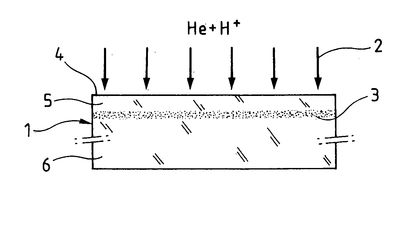
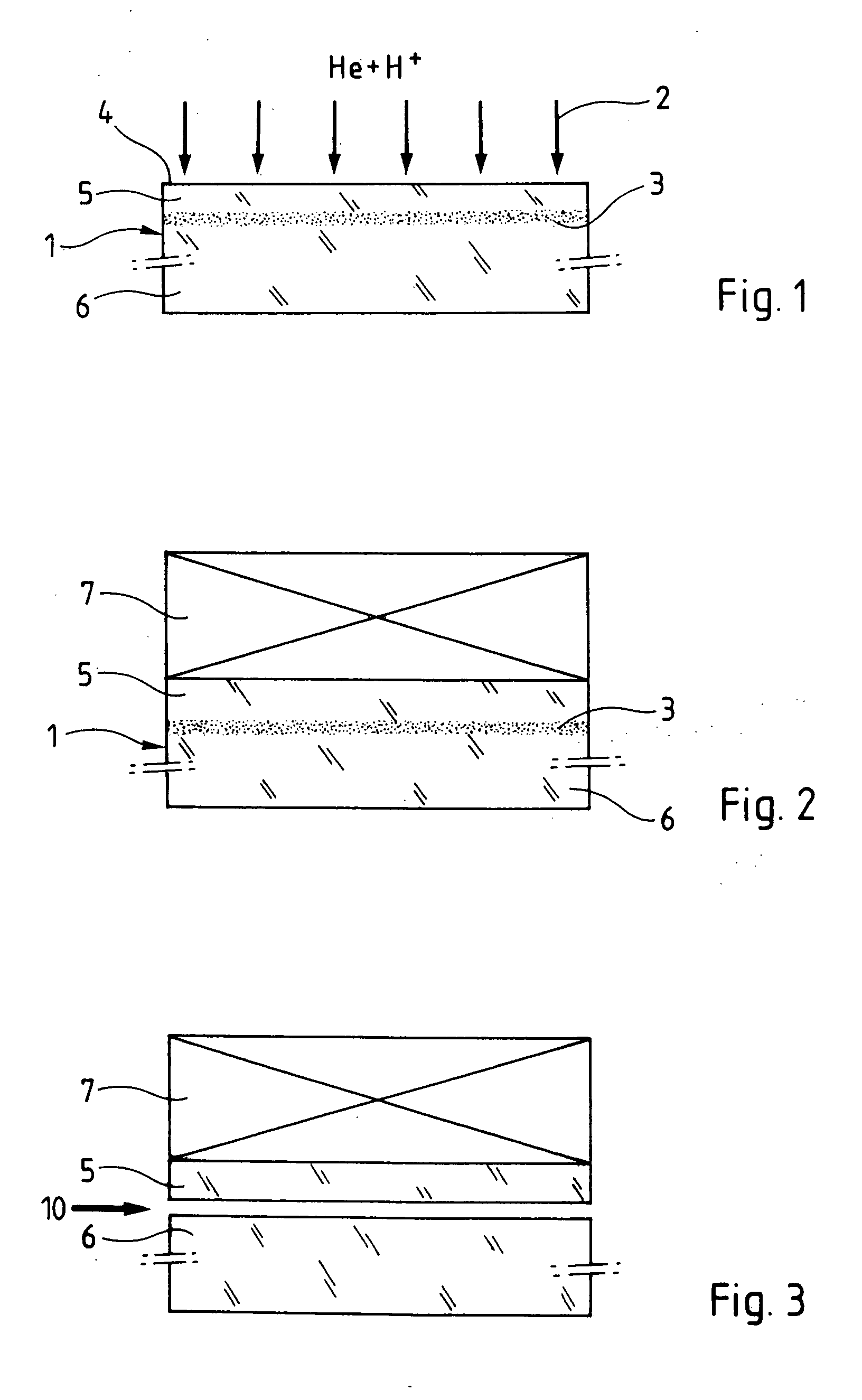
[0066] According to a first embodiment of the invention, a substrate of Si (˜700 μm) comprising a layer of thermal SiO2 on the surface (for example 145 nm) was implanted initially with helium atoms under implantation conditions of 70 keV at 1×10¹⁶ ions / cm2, and then implanted with hydrogen atoms under implantation conditions of 30 keV at 4.25×10¹⁶ ion s / cm2. This source substrate was next joined to a target substrate of Si (˜700 μm) by direct bonding. A heat treatment around 350° C. induced the growth of cavities of platelet type localized at the hydrogen concentration peak. The helium atoms play the role of atoms trapped thereat and create a maximum of defects of platelet type at the applied temperature. After a certain time (for example 2 hours), with scarcely the commencement of insertion of a blade between the bonding interfaces in the form of a shock, catastrophic splitting at the location of maximum hydrogen concentration led to the transfer of the thin film of Si onto the tar...


PUM


Abstract

The invention relates to a method of catastrophic transfer of a thin film including implanting in a source substrate a first species of ions or gas at a given depth and a second species of ions or gas, the first species being adapted to generate defects and the second species being adapted to occupy those defects. The process further includes applying a stiffener in intimate contact with the source substrate, applying a heat treatment to that source substrate, at a given temperature for a given time, so as to create, substantially at the given depth, a buried weakened zone, without initiating the thermal splitting of a thin film, and applying a localized amount of energy, for example mechanical stresses, to that source substrate so as to provoke the catastrophic splitting of a thin film, the thin film having a substantially planar face opposite to the face surface of the source substrate.

Description

RELATED APPLICATIONS [0001] This application claims priority to U.S. provisional patent application Ser. No. 60 / 531,591, filed Dec. 19, 2003.FIELD OF THE INVENTION [0002] The invention relates, generally, to methods for forming a thin-film in a semiconductor substrate and, more particularly, to a method of transferring an ultra-thin film (the term thin film is also used) at low temperature by the method of co-implantation. The invention has applications in particular in the fields of micro-electronics, micro-mechanics, optics and integrated electronics. BACKGROUND [0003] As is known, splitting a thin film may be achieved by implantation of chemical species in a source substrate, for example of silica, to induce the formation of a zone of defects at a particular depth. These defects may be micro-bubbles and / or platelets and / or micro-cavities and / or dislocation loops and / or other crystalline defects, locally disrupting the crystalline quality of the material; their nature, density and...

Claims


Application Information

Patent Timeline
IPC IPC(8): H01L21/30H01L21/762
CPCH01L21/76254
Inventor NGUYEN, NGUYET-PHUONGCAYREFOURCQ, IANLAGAHE-BLANCHARD, CHRISTELLE
Owner COMMISSARIAT A LENERGIE ATOMIQUE ET AUX ENERGIES ALTERNATIVES
Why Eureka
Try Eureka