Eureka AIR delivers breakthrough ideas for toughest innovation challenges, trusted by R&D personnel around the world.

Dye-sensitized solar cell

Inactive Publication Date: 2005-07-14
SHARP KK
View PDF8 Cites 12 Cited by
  • Summary
  • Abstract
  • Description
  • Claims
  • Application Information

AI Technical Summary

Benefits of technology

[0016] The inventor of the present invention eagerly studied dye-sensitized solar cells while taking the above problems into account and found that, when the electrolytic solution contains a particular heterocyclic

Problems solved by technology

Producing a silicon single crystal and amorphous silicon, however, requires enormous amounts of energy and, in order to recover energy consumed for manufacturing cells, electric power generation needs to be carried out continuously for nearly a ten-year long period.
When TBP is used, however, a marked decrease in short-circuit current is observed, and the actually obtained open-circuit voltage is low when compared with a theoretically expected open-circuit voltage.
Also, the addition of the compound will lead to an increase in the viscosity of a solvent in the electrolytic solution, which results in a marked decrease in short-circuit current and in fill factor and thus a noticeable decrease in conversion efficiency.

Method used


Image

  • Dye-sensitized solar cell
  • Dye-sensitized solar cell
  • Dye-sensitized solar cell

Examples


examples

[0074] The invention will be described in more detail with reference to the following examples; however, the invention is not limited to the examples.

[0075] Heterocyclic Compound (A)

examples a-1 to a-8

and Comparative Examples 1 to 7

[0076] Using electrolytic solutions containing the heterocyclic compounds in Table 1 in the concentrations shown in the table, dye-sensitized solar cells were manufactured as follows.

TABLE 1No.Heterocyclic compound% By volume*Example A-1Tetrahydrofuran10Example A-2Tetrahydrofuran40Example A-32-Methyl-tetrahydrofuran30Example A-4Pyran20Example A-5Pyran40Example A-6Tetrahydropyran20Example A-7Furan5Example A-82-Methyl-furan20Comp. Ex. 1Tetrahydrofuran70Comp. Ex. 2Pyran70Comp. Ex. 3Tetrahydropyran70Comp. Ex. 41,4-Dioxane90Comp. Ex. 5Trioxane90Comp. Ex. 6Furan70Comp. Ex. 7Not added

*Remainder is a mixture of acetonitrile, DMPII, lithium iodide, iodide and TBP.

[0077] Formation of a Porous Semiconductor Layer

[0078] First, a commercially available titanium oxide paste (trade name: Ti-Nanoxide D, average particle diameter: 13 nm, made by Solaronix Co., Swiss) was applied by a doctor blade method to a transparent conductive film of SnO2 formed by vapor depos...

examples b-1 to b-10

[0089] Dye-sensitized solar cells were manufactured in the same manner as in Examples A-1 to A-8 except that the heterocyclic compounds in Table 3 were contained in the electrolytic solutions in the concentrations shown in the table.

TABLE 3No.Heterocyclic compound% By volumeExample B-14-Methyl-1,3-dioxolane20Example B-21,3-Dioxolane20Example B-31,3-Dioxane40Example B-41,4-Dixoane5Example B-51,4-Dixoane30Example B-62H-1,3-Dioxole60Example B-73H-1,2-Dioxole55Example B-8Dioxene70Example B-91,4-Dioxin20Example B-10Trioxane5Comp. Ex. 7Not added

[0090] The photoelectric conversion efficiencies of the dye-sensitized solar cells thus obtained were evaluated in the same manner as in Examples A-1 to A-8. The results are shown in Table 4.

TABLE 4No.Jsc (mA / cm2)Voc (V)FFEffi. (%)Example B-116.50.7550.7108.84Example B-216.80.7560.7279.23Example B-317.90.7550.7099.58Example B-418.10.7340.7349.75Example B-517.80.7660.7219.83Example B-616.40.7820.7119.12Example B-716.50.7790.7129.15Example B-816....


PUM


Abstract

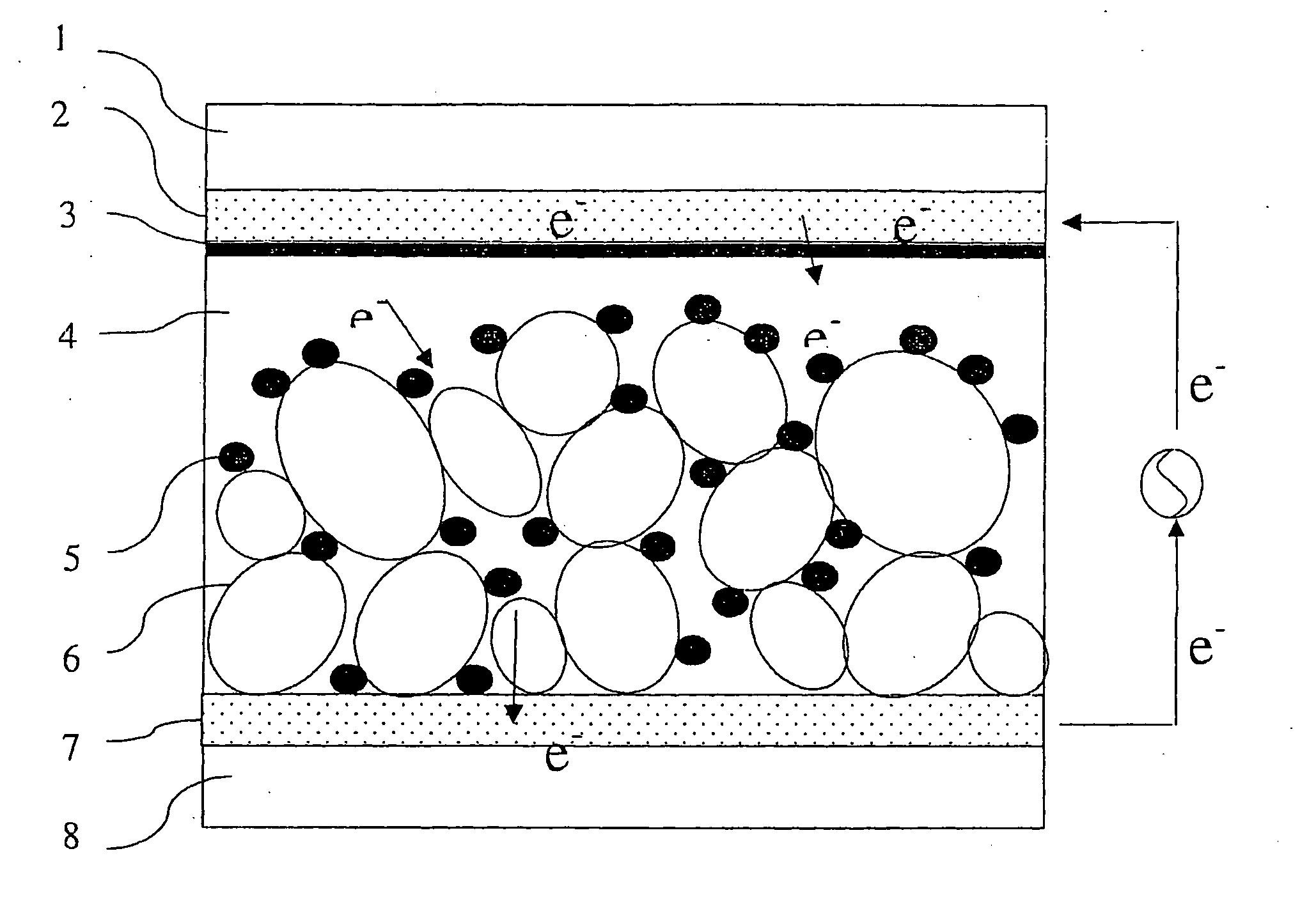
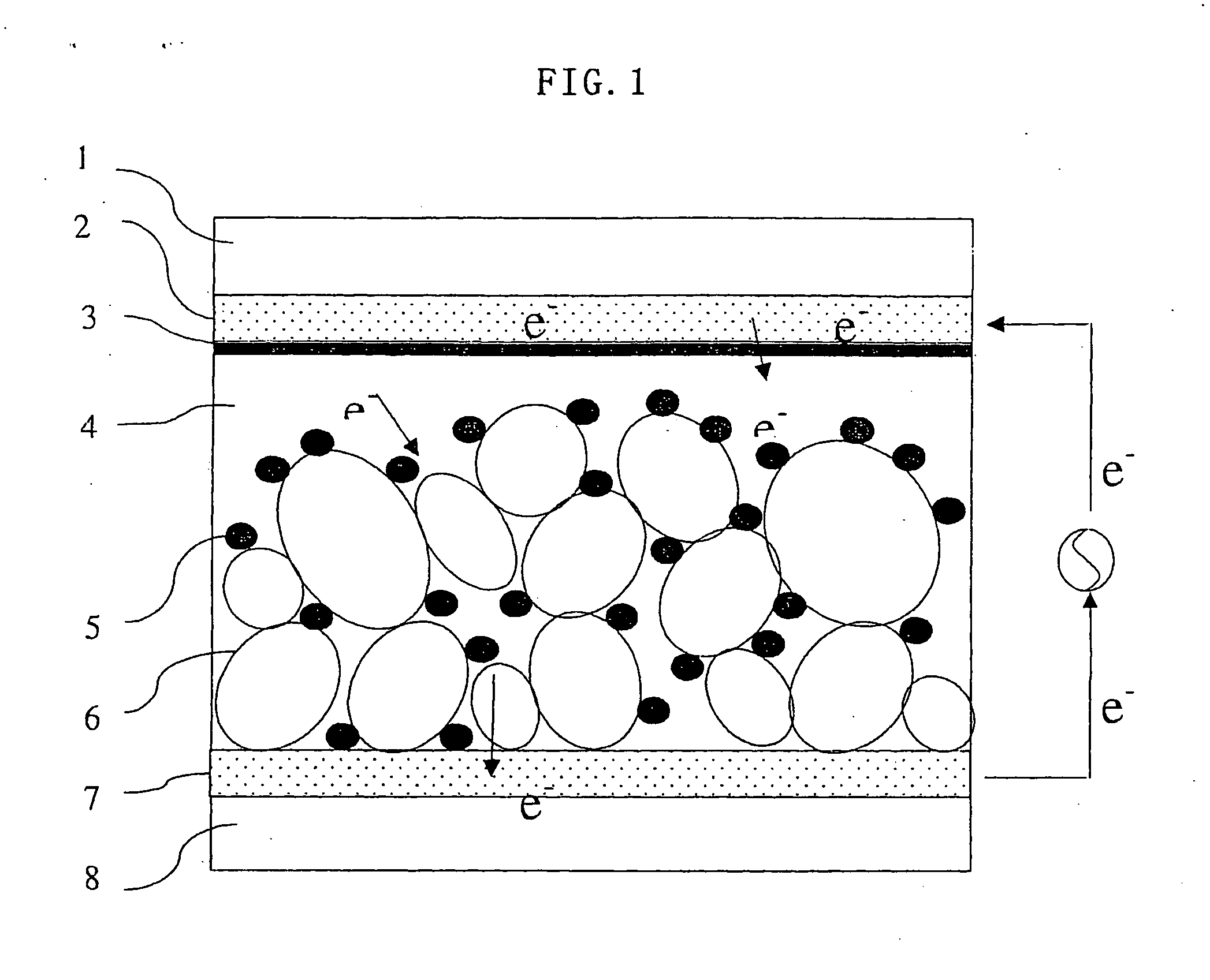
The present invention provides a dye-sensitized solar cell including: a transparent electrode; a counter electrode; a porous semiconductor layer having a dye sensitizer adsorbed therein; and a carrier transport layer containing an electrolytic solution therein, the porous semiconductor layer and the carrier transport layer being located between the transparent electrode and the counter electrode, wherein the electrolytic solution contains a heterocyclic compound comprising a heteroatom in the ring.

Description

CROSS-REFERENCES TO RELATED APPLICATIONS [0001] This application is related to Japanese applications Nos. 2003-407899, 2003-407908 and 2003-407916 filed on Dec. 5, 2003 whose priorities are claimed under 35 USC 119, the disclosures of which are incorporated by reference in their entirety. BACKGROUND OF THE INVENTION [0002] 1. Field of the Invention [0003] The present invention relates to a dye-sensitized solar cell and, more particularly, to a dye-sensitized solar cell with a high conversion efficiency that has a carrier transport layer containing an electrolytic solution. [0004] 2. Description of Related Art [0005] Conventionally, as a device for directly converting light energy to electric energy, crystalline silicon solar cells have been well known and have been utilized in the field of weak power consumption, and as an independent power source and also as a power source for use in aerospace. Crystalline silicon solar cells are made mainly of a silicon single crystal or amorphous...

Claims


Application Information

Patent Timeline
IPC IPC(8): H01G9/20H01L31/00
CPCH01G9/2004Y02E10/542H01G9/2031
Inventor FUKUI, ATSUSHIYAMANAKA, RYOHSUKEKOMIYA, RYOICHIHAN, LIYUAN
Owner SHARP KK
Why Eureka
Eureka Blog
Learn More