Amplifier predistortion and autocalibration method and apparatus

an amplifier and autocalibration technology, applied in the direction of amplifier modifications to reduce non-linear distortion, gain control, pulse technique, etc., can solve the problems of variable gain amplifiers producing varying phase delays based on gain value, real amplifiers do not have the characteristics of ideal amplifiers, and amplifiers typically contribute nonlinear distortion. , to achieve the effect of reducing distortion, improving the performance of amplifiers, and improving the efficiency and performance of communication devices

Active Publication Date: 2005-07-21
QUALCOMM INC
View PDF3 Cites 187 Cited by
  • Summary
  • Abstract
  • Description
  • Claims
  • Application Information

AI Technical Summary

Benefits of technology

[0006] It is desirable to increase the performance of an amplifier by decreasing the amount of distortion that the amplifier contributes to the signal being amplified. Minimizing the effects of amplifier distortion allows for more efficient and better performing communication device implementations.

Problems solved by technology

Of course, a real amplifier does not have the characteristics of an ideal amplifier.
However, an amplifier typically contributes some nonlinear distortion.
Additionally, a variable gain amplifier may produce varying phase delays based on the gain value.
However, for other applications, the amount of signal distortion contributed by the amplifier may adversely affect the signal quality to an extent that a communication link is substantially degraded.
The variation in the amplitude envelope poses additional constraints on amplifier performance.
Wireless transmitters having amplifiers that were originally configured to operate using constant envelope GMSK modulation may not perform satisfactorily with 3π / 8 PSK modulation.

Method used


Image

  • Amplifier predistortion and autocalibration method and apparatus
  • Amplifier predistortion and autocalibration method and apparatus
  • Amplifier predistortion and autocalibration method and apparatus

Examples


Embodiment Construction

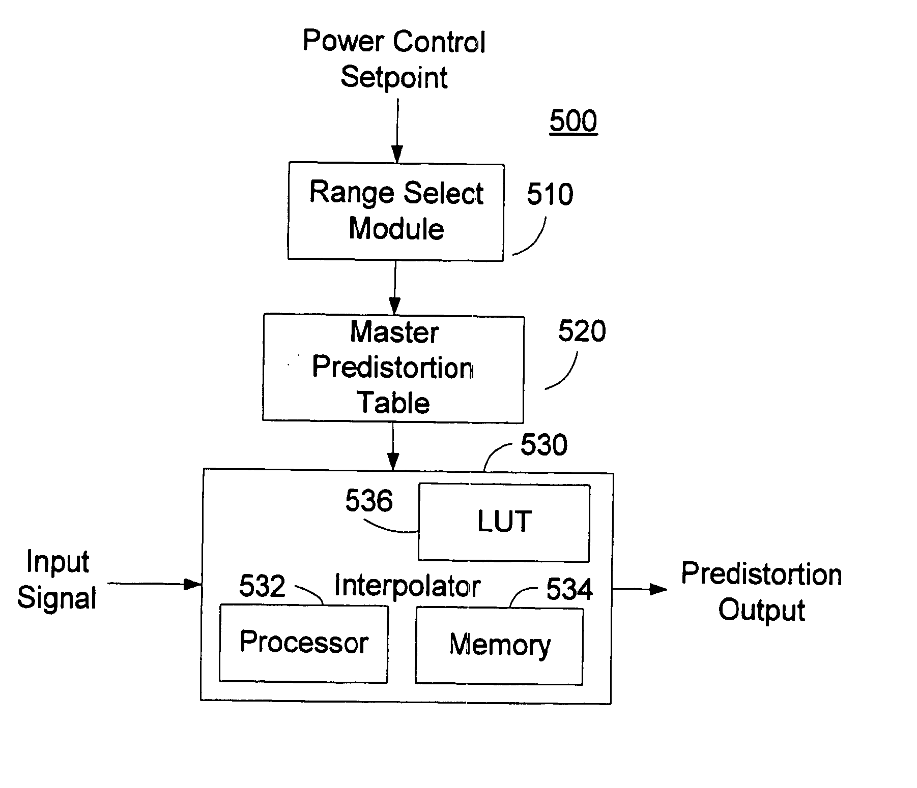
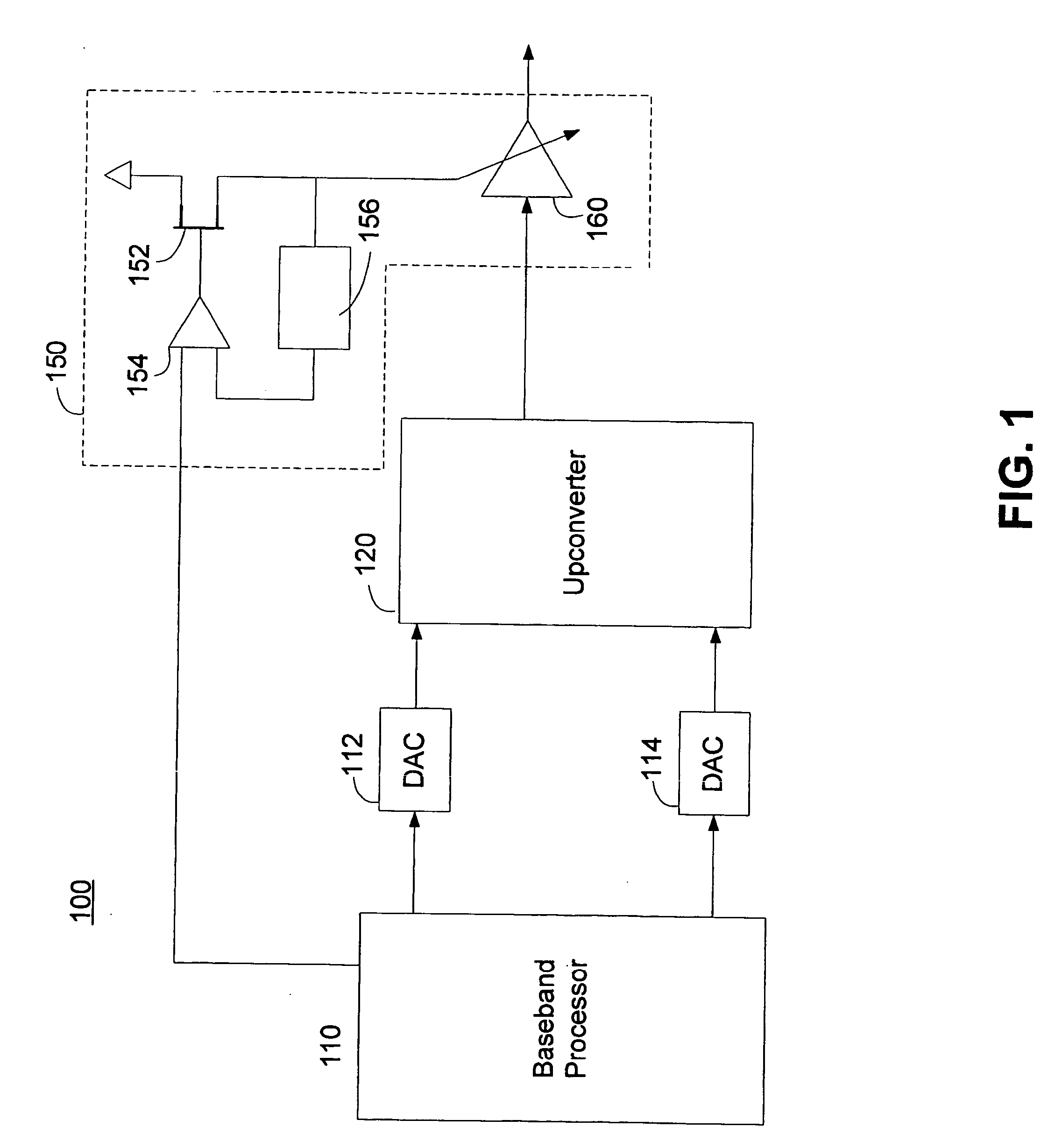
[0023] The effects of amplifier distortion can be reduced to acceptable levels by predistorting the signals to the amplifier. Signal distortion contributed by a variable gain power amplifier in a wireless communication device can be minimized by predistorting a gain control signal, a phase of the input signal, or a combination of the two.

[0024] In order to compensate for amplifier distortion effects, the amplifier can be characterized by measuring the performance of the amplifier. Alternatively, amplifier characteristics may be supplied by a manufacturer or can be generalized across multiple amplifiers using statistical sampling, statistical characterization, or simulations. The amplifier gain characteristics or gain transfer function can be determined. Additionally, the amplifier phase characteristics can be determined over a gain range of the amplifier.

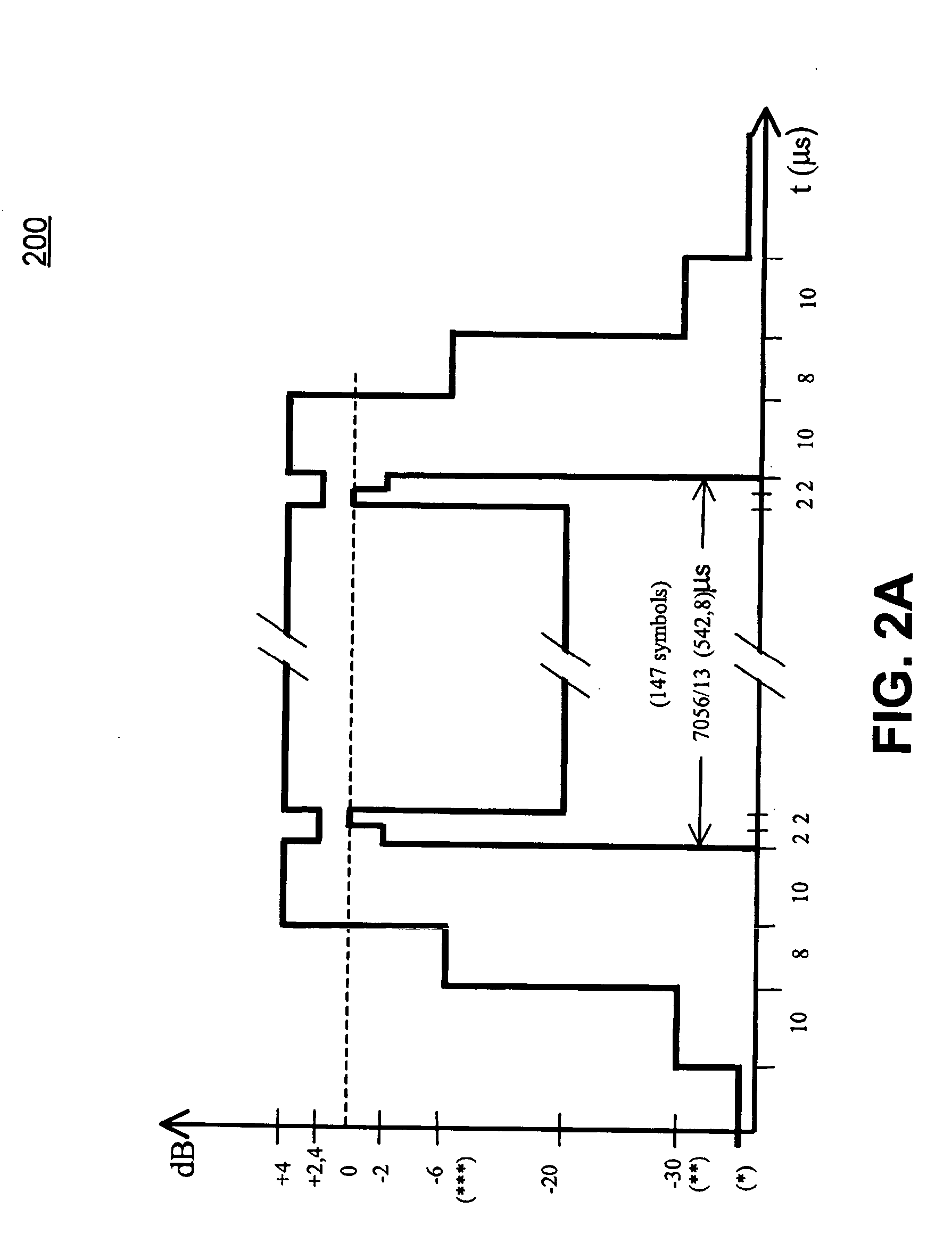
[0025] The amplifier characteristics may be determined at a single frequency or at multiple frequencies. Additionally, the ampli...


PUM


Abstract

Methods and apparatus for amplifier AM and PM predistortion and autocalibration. AM and PM amplifier distortion can be corrected using predistortion. The AM and PM distortion characteristics of the amplifier are determined using an autocalibration technique. The amplifier characteristics can be stored in distinct look up tables. Alternatively, the inverse of the amplifier characteristics can be stored in distinct look up tables. Signals that are to be amplified are characterized in polar format having a phase component with a normalized magnitude and a magnitude component. The phase component can be predistorted by applying the inverse of the PM distortion characteristics to the signal. Similarly, the magnitude component can be predistorted by applying the inverse of the AM distortion characteristics to the signal. The predistorted phase component can be amplified using the previously characterized amplifier. The predistorted magnitude component can be used to set the gain of the previously characterized amplifier.

Description

CROSS-REFERENCES TO RELATED APPLICATIONS [0001] This application claims the benefit of U.S. Provisional Application No. 60 / 537,145, filed Jan. 16, 2004, entitled ENVELOPE ELIMINATION AND RESTORATION (EER) WITH PRE-DISTORTION & AUTO-CALIBRATION FOR EDGE TRANSMITTER; which is hereby incorporated herein by reference in its entirety.BACKGROUND OF THE DISCLOSURE [0002] Variable gain amplifiers are commonly used in communication devices. Such amplifiers can be used, for example, in the receive path of a wireless communication device as part of an Automatic Gain Control (AGC) circuit. The variable gain amplifier can be used to maintain a range of intermediate frequency amplitudes for subsequent processing. Variable gain amplifiers may also be used in the transmit path of a wireless communication device. A variable gain amplifier may be used, for example, to set the output power of a transmitted signal. [0003] Of course, a real amplifier does not have the characteristics of an ideal amplifi...

Claims


Application Information

Patent Timeline
Patent Type & Authority Applications(United States)
IPC IPC(8): H03F1/02H03F1/32H03G3/30
CPCH03F1/0222H03F1/3247H03G3/3047H03F2201/3233H03F1/3282
Inventor RAGHUPATHY, ARUNSEE, PUAY HOESAHOTA, GURKANWAL KAMALREEVES, ROBERTPETERZELL, PAUL E.
Owner QUALCOMM INC
Why Eureka
Try Eureka