Optical inertial reference unit for kilohertz bandwidth submicroradian optical pointing and jitter control

a submicroradian optical and inertial reference technology, applied in the field of optical inertial reference units for kilohertz bandwidth submicroradian optical pointing and jitter control, can solve the problems of reducing stabilization performance or complicating control, affecting the accuracy of optical measurements, etc., to achieve high performance

Active Publication Date: 2005-07-28
A TECH
View PDF5 Cites 14 Cited by
  • Summary
  • Abstract
  • Description
  • Claims
  • Application Information

AI Technical Summary

Benefits of technology

[0015] The preferred embodiment of this apparatus achieves high performance through low-noise high-bandwidth inertial rate sensors, a small symmetric platform, and a high-bandwidth active stabilization servo. In addition, the preferred embodiment of this apparatus incorporates a digital feedback control system that accepts signals from the inertial sensors on the platform, the actuators, the linear displacement sensors, a

Problems solved by technology

At sub-microradian levels of accuracy, significant disturbances to the line of sight originate within the optical system itself.
This is undesirable for several reasons: (1) current technologies for high-accuracy low-drift-rate DC sensors result in large and massive sensors; these large heavy sensors necessitate increased size and weight of the platform which limits control bandwidth, (2) high-accuracy low-drift-rate DC sensors attached to the platform introduce asymmetries to the moments of inertia which further complicate the controls, (3) since high-perfo

Method used


Image

  • Optical inertial reference unit for kilohertz bandwidth submicroradian optical pointing and jitter control
  • Optical inertial reference unit for kilohertz bandwidth submicroradian optical pointing and jitter control
  • Optical inertial reference unit for kilohertz bandwidth submicroradian optical pointing and jitter control

Examples


Embodiment Construction

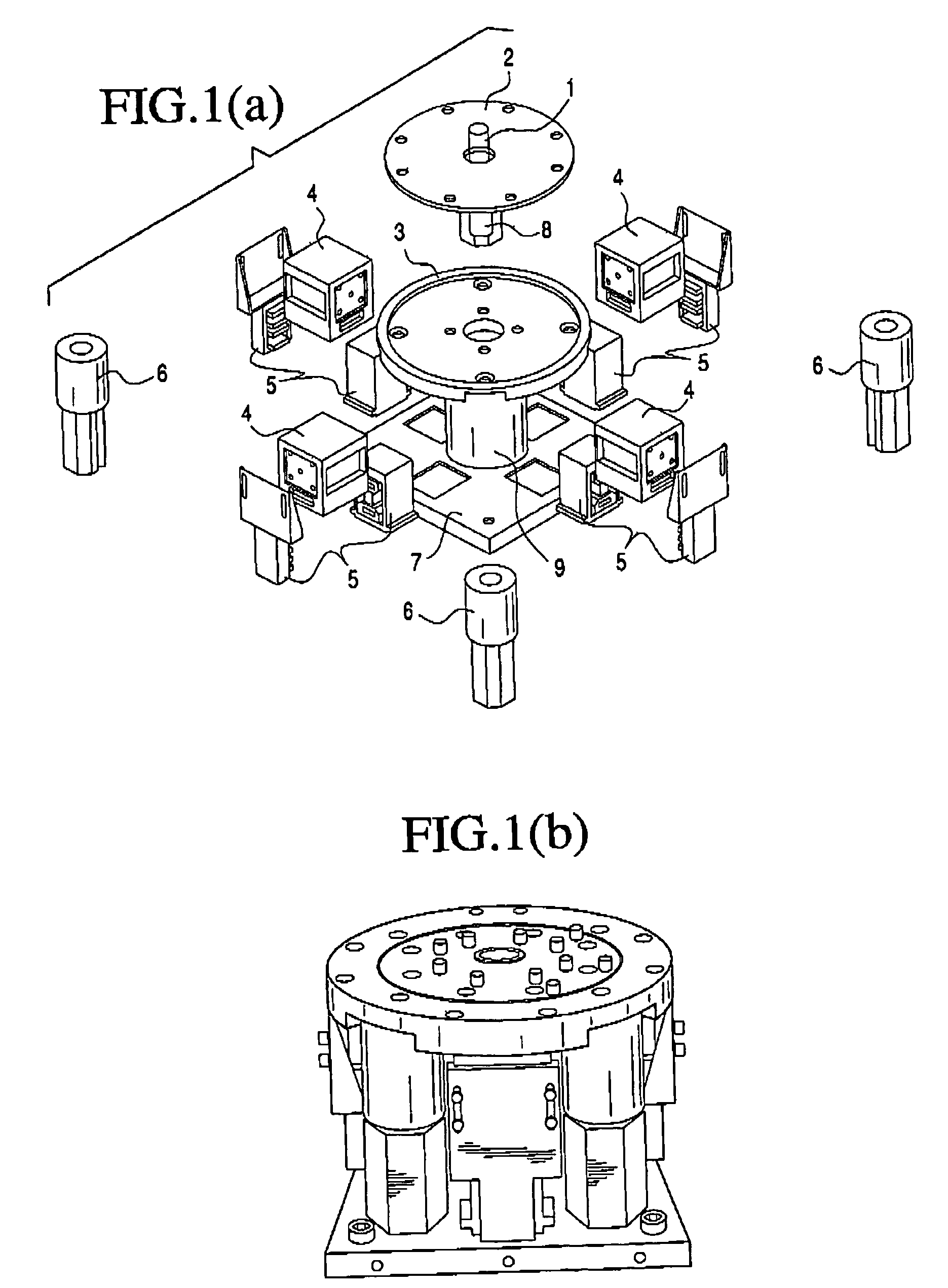
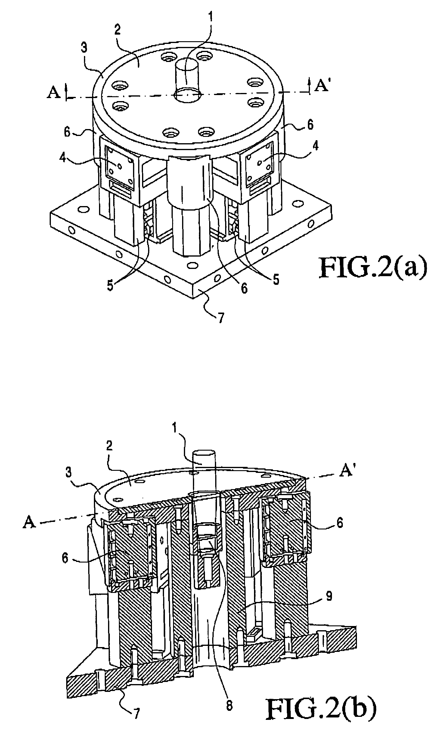
[0032] Referring to the drawing figures, FIG. 1A illustrates an exploded mechanical layout of an exemplary embodiment of the apparatus, while FIG. 1B illustrates this embodiment as an integrated device. FIG. 2A and 2B illustrate a composite mechanical view and a cross-section of this same exemplary embodiment.

[0033] The base 7 is a plate that attaches rigidly to the structure of an optical system external to this apparatus. The platform comprises an optical assembly 2 rigidly attached to a plate 3. In this embodiment, the optical subassembly includes an attached fiber optic interface 8 for accepting and shaping the beam from an optical fiber from a laser light source (not shown). An optical reference beam 1 is emitted perpendicular to the surface of the platform.

[0034] The stable platform 3 is attached to the base 7 through a mechanical flexure 9 that allows motion in two directions that correspond to tip and tilt of the platform relative to the base. Note that in this embodiment,...


PUM


Abstract

A device providing an inertially stabilized laser beam as an optical reference. The device consists of a base and a small stabilized optical platform that emits the laser beam. The platform connects to the base through a mechanical flexure that allows relative motion in two axes. High-bandwidth angular rate sensors affixed to the platform measure platform motion in inertial space. Linear displacement sensors measure relative motion between base and platform. A closed-loop control system accepts these sensor measurements and command actuators that null the sensed platform motions, maintaining the optical platform fixed in inertial space. The digital controller implements a Sensor Blending Kalman Filter that blends high frequency signals from the platform with low frequency signals from a DC sensor (gyroscope) external to this device but affixed to the common base. The controller enables both stabilization of the laser beam and commanded pointing of the beam in inertial space.

Description

[0001] This application is based on provisional application No. 60 / 481,829, filed Dec. 24, 2003, and claims priority thereto.BACKGROUND OF THE INVENTION [0002] The present invention relates generally to electro-optical systems, and more specifically, to systems that require line of sight pointing and stabilization. [0003] Precision optical instruments mounted on mobile platforms need to point accurately and reject disturbances to the line of sight. At sub-microradian levels of accuracy, significant disturbances to the line of sight originate within the optical system itself. To sample and correct for these errors requires the creation of an optical reference in inertial space, similar to a fixed star. Such a reference allows detection and correction of internal jitter sources along the optical train, and this “virtual star” supports both increased pointing accuracy and line of sight stabilization requirements. [0004] A previously developed system approach developed by the assignee o...

Claims


Application Information

Patent Timeline
IPC IPC(8): G01C21/16G01J1/20G02B27/64
CPCG02B27/644G01C21/16G01C21/166
Inventor ECKELKAMP-BAKER, DANSEBESTA, HENRY R.
Owner A TECH
Why Eureka
Try Eureka