Energy network

Inactive Publication Date: 2005-07-28
STUART ENERGY SYST
View PDF60 Cites 131 Cited by
  • Summary
  • Abstract
  • Description
  • Claims
  • Application Information

AI Technical Summary

Benefits of technology

[0058] Providing a supplemental load to permit base load plants to operate at their optimum efficiency and lowest emissions during periods of low demand.
[0059] The network operator could also work closely with the other power generators on the public grid to make power purchases bilaterally to reduce emissions through demand management of specific generators such as natural gas fired generation where a significant drop in efficiency occurs when power levels are reduced and hence a significant increase occurs in specific emissions (emission gm per kWh). By increasing loads through hydrogen production the generator can be more efficient and hence produces lower specific emissions. In this way the network can also act to improve the efficiency of the public grid.
[0060] These actions could be formally contracted by selling ancillary services to the grid. Because the network can adjust energy flows between captive power plants and hydrogen production in a very precise fashion and on a “real-time” basis the system can provide short-term operating reserves to the grid and even “spinning reserves” by making a certain proportion of the demand for fuel production a “responsive” load. In this way, in the event of outage of a generator or transmission line and the network is contracted to provide operating reserves, the network controller would be notified and would turn down the rate of hydrogen production to make

Problems solved by technology

One of the most frequently cited impediments to the development of gaseous hydrogen vehicles is the lack of a fuel supply infrastructure.
Because of the relatively low volume density of gaseous hydrogen it is not cost effective to handle gaseous hydrogen in the same way as liquid fuels using central production at a refinery and transporting fuel in fuel tankers.
Also unlike natural gas which is delivered to the customer through a pipeline, there is no large-scale pipeline delivery infrastructure for hydrogen.
In most electricity market designs electricity is a commodity and it is often difficult to differentiate and assign particular sources of electricity generation to a particular electricity demand.
Hence it is difficult to precisely define the emission characteristics of power used in a particular application.
H

Method used


Image

  • Energy network
  • Energy network
  • Energy network

Examples


Embodiment Construction

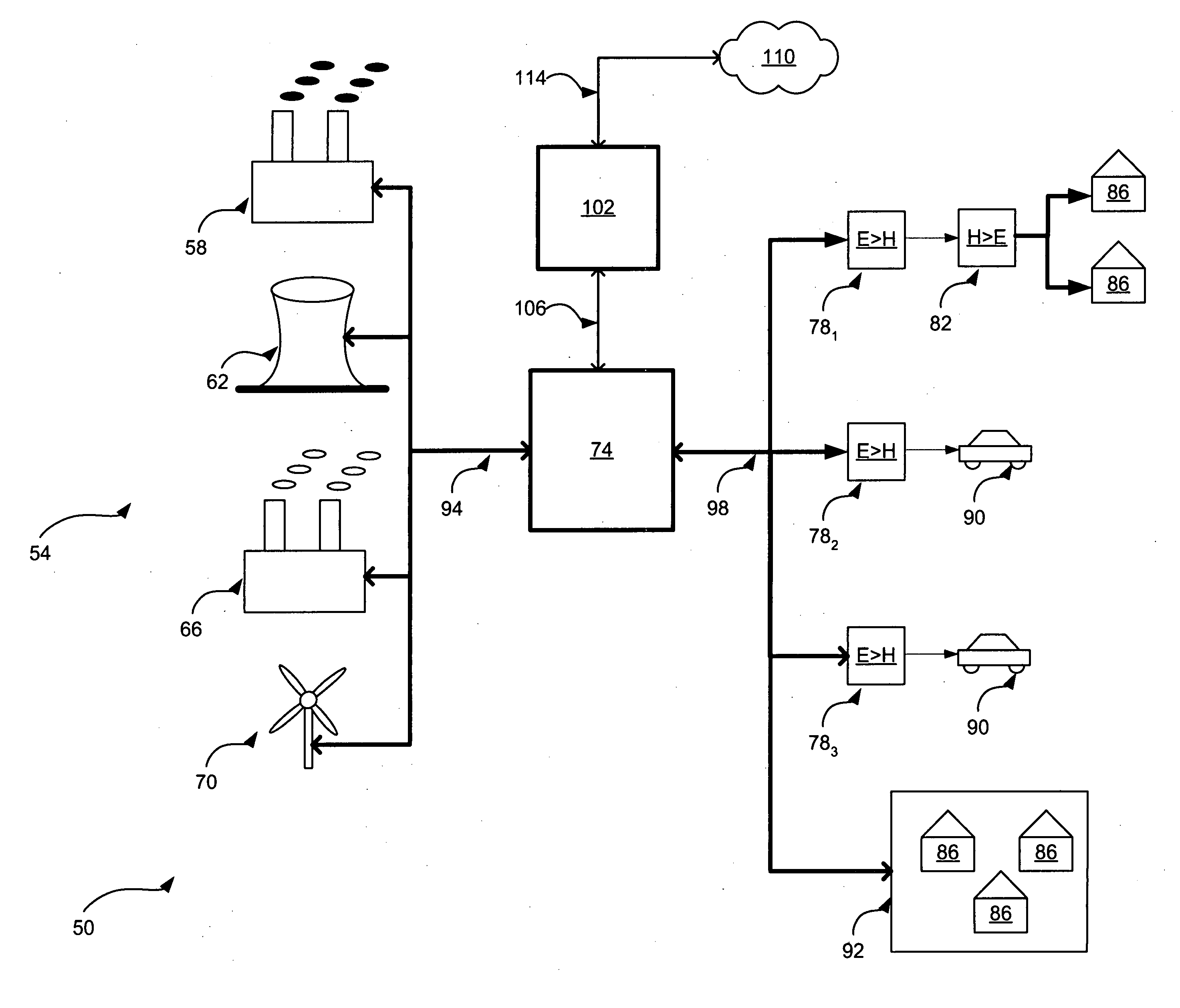
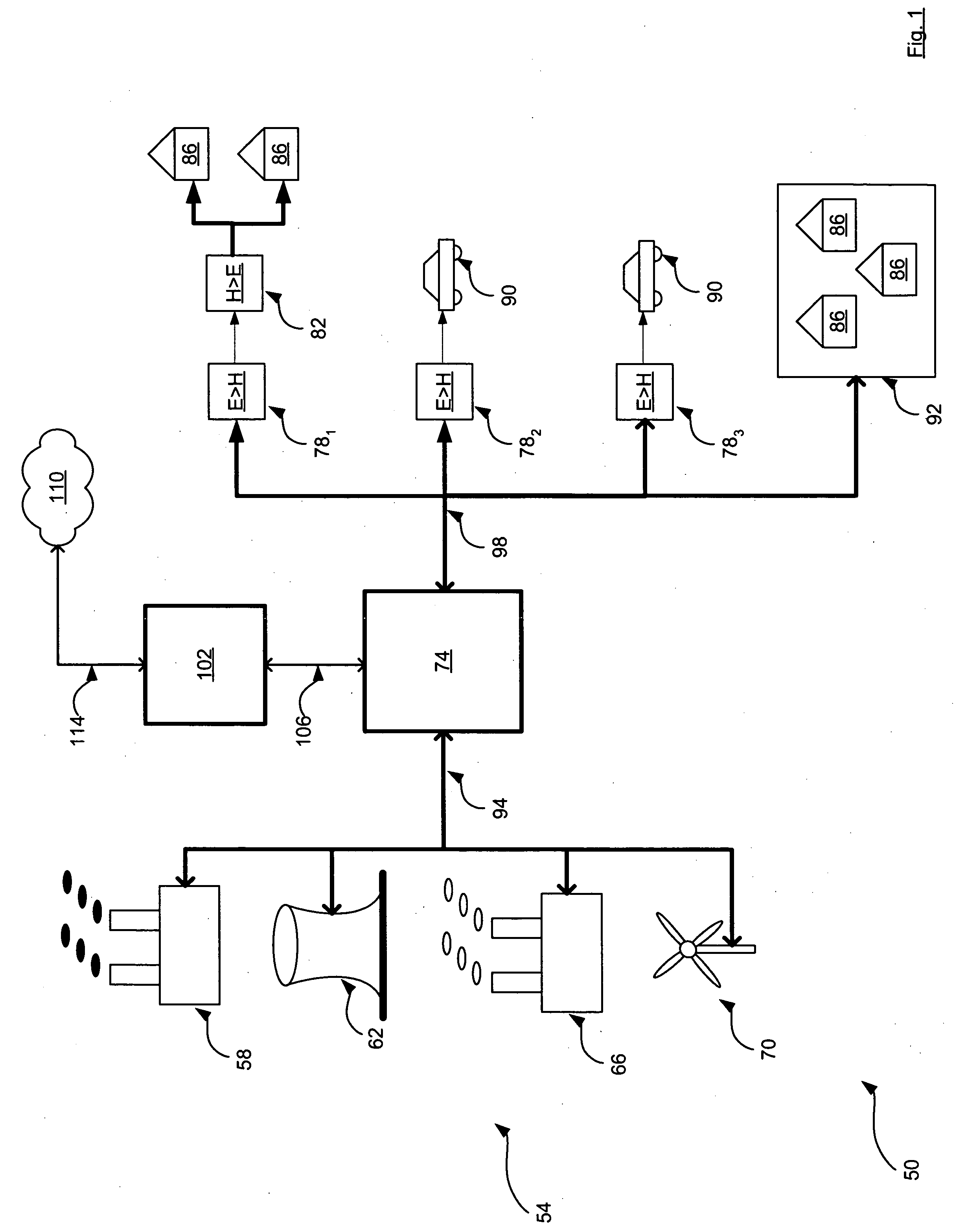
[0073] Referring now to FIG. 1, an energy network is indicated generally at 50. Network 50 includes a plurality of electrical generating stations 54. In a present embodiment, electrical generating stations include a coal power plant 58, a nuclear power plant 62, a natural gas power plant 66, and a wind-farm 70. As will be discussed in greater detail below, each electrical generating station 54 has a profile relating to the amount of energy it can generate, and another profile relating to the environmental pollutants associated with that energy generation.

[0074] Network 50 also includes a power grid 74, which is substantially the same as any conventional electrical power distribution grid, including transmission lines, power stations, transformers, etc. as is currently known or may become known.

[0075] Network 50 also includes a plurality of electrolysers 78, that are connected to grid 74, and which are operable to convert electricity from grid 74 into hydrogen, and store that hydro...


PUM


Abstract

An energy network is provided. An embodiment includes a network having a plurality of power stations and a plurality of loads interconnected by an electricity grid. The loads include electrolysers. The network also includes a controller that is connected to both the stations and the loads. The controller is operable to vary the available power from the power stations and/or adjust the demand from the electrolysers to provide a desired match of availability with demand and produce hydrogen as a transportation fuel with specific verifiable emission characteristics

Description

PRIORITY CLAIM [0001] The present application claims priority from Canadian Patent Application 2,455,689 filed on Jan. 23, 2004, the contents of which are incorporated herein by reference. FIELD OF THE INVENTION [0002] The present invention is directed to the generation and distribution of energy and more particularly to energy networks. BACKGROUND OF THE INVENTION [0003] Hydrogen can be used as a chemical feed-stock and processing gas, or as an energy carrier for fueling vehicles or other energy applications. Hydrogen is most commonly produced from conversion of natural gas by steam methane reforming or by electrolysis of water. Comparing hydrogen as an energy carrier with hydrocarbon fuels, hydrogen is unique in dealing with emissions and most notably greenhouse gas emissions because hydrogen energy conversion has potentially no emissions other than water vapour. [0004] However emissions that have global impact, such as CO2, need to be measured over the entire energy cycle, which ...

Claims


Application Information

Patent Timeline
IPC IPC(8): C25B1/04F17D1/04F17D5/08H01M8/0612H01M8/0656H02J3/14H02J3/38
CPCF17D1/04F17D5/08H01M8/04089H01M8/04313H01M8/04694Y02E60/528H01M8/0656H01M8/184H02J3/14H02J3/38Y02E60/34H01M8/04955Y02P90/45Y02E60/50Y02E60/36H02J2310/58H02J2310/64H02J3/144Y04S50/10
Inventor FAIRLIE, MATTHEW
Owner STUART ENERGY SYST
Why Eureka
Try Eureka