Light source device and exposure equipment using the same

Active Publication Date: 2005-08-04
GIGAPHOTON
View PDF5 Cites 118 Cited by
  • Summary
  • Abstract
  • Description
  • Claims
  • Application Information

AI Technical Summary

Benefits of technology

[0017] According to the present invention, since the magnetic field generating means that operates when supplied with current is provided, the collector mirror can be protected from debris that is considered harmful to a mirror coating by generating a strong magnetic field within collection optical system while securin

Problems solved by technology

The melted solid material radiates in large quantity as debris of more than several micrometers in diameter, and that causes damage to the collector mirror (specifically, to the mirror coating) to reduce the reflectance thereof.
On the other hand, in the case where a gas is used as the target, although an amount of debris is reduced, the conversion efficiency from the power supplied to the driving laser into the power of EUV light is reduced.
However, the fact is that the debris radiating from plasma flies in almost all directions.
Therefore, assuming that the traveling velocity of plasma is several hundreds of meters per second that is the same as the traveling velocity of the t

Method used


Image

  • Light source device and exposure equipment using the same
  • Light source device and exposure equipment using the same
  • Light source device and exposure equipment using the same

Examples


first embodiment

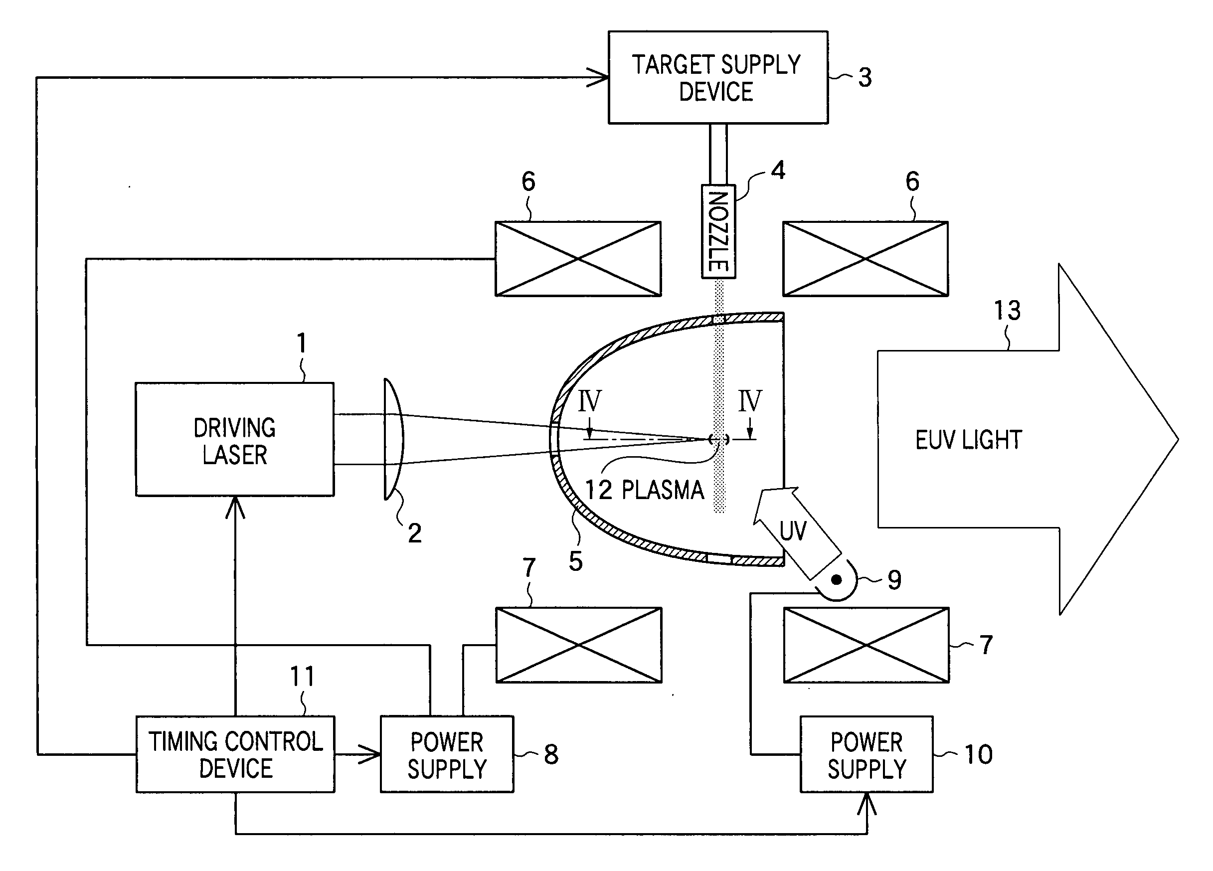
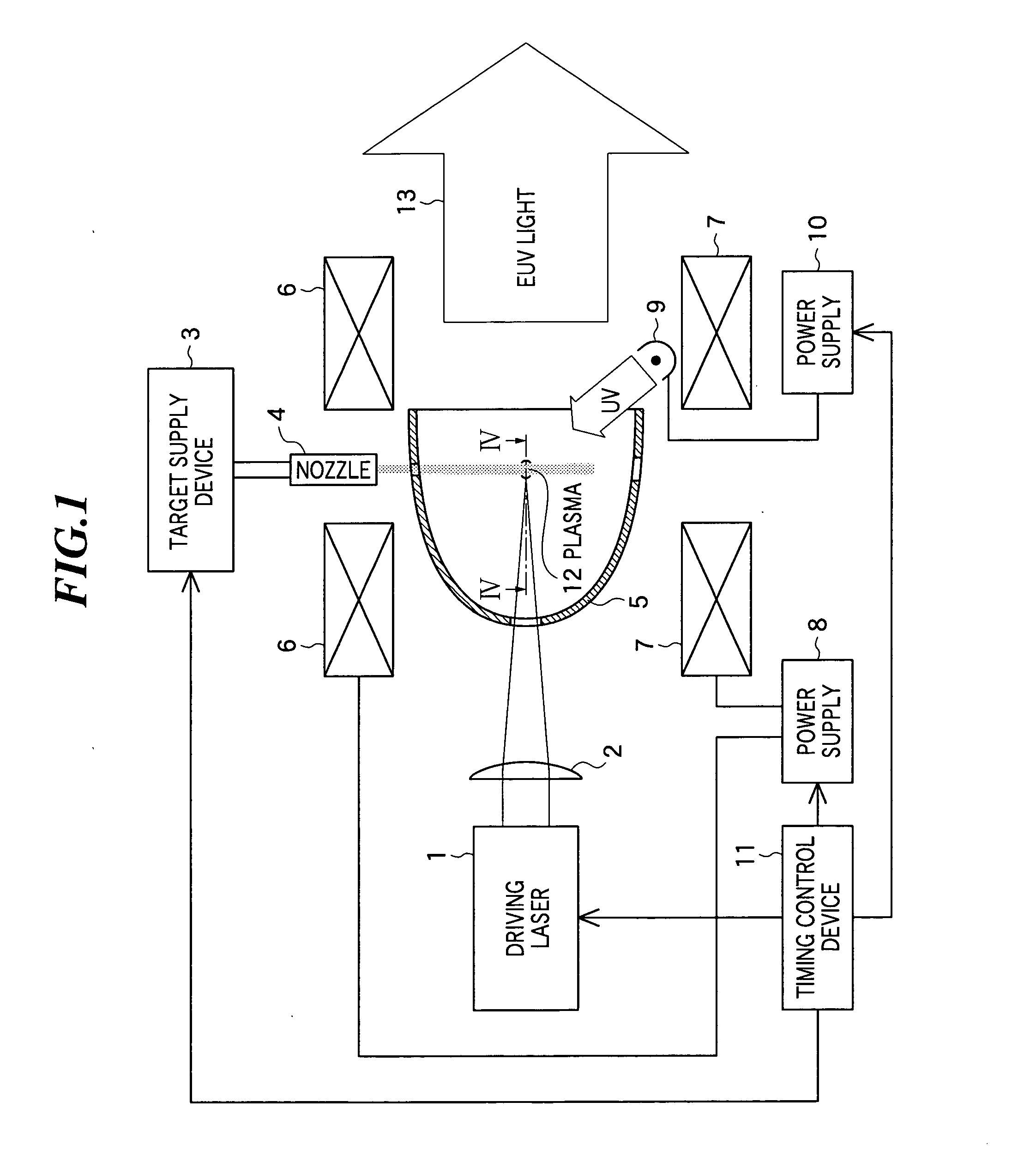
[0033] In FIG. 1, the constitution of a light source device according to the present invention is shown. This light source device includes a driving laser 1 as a laser unit for generating a laser beam and an application optical system for collecting the laser beam generated by the driving laser 1. In the embodiment, the application optical system is constituted by a focusing lens 2. As the focusing lens 2, a plano-convex lens, cylindrical lens, or a combination of those lenses can be used.

[0034] Further, the light source device includes a target supply device 3 as a target supply unit for supplying a material to become a target to which a laser beam is applied, and a nozzle 4 for injecting the material supplied from the target supply device 3, and further includes a collection optical system for collecting extreme ultra violet (EUV) light radiating from plasma and emitting the light. In the embodiment, the collection optical system is formed by a collector mirror 5. As the collector...

second embodiment

[0060] Next, a light source device according to the present invention will be described by referring to FIG. 8.

[0061] In FIG. 8, the constitution of the light source device according to the second embodiment of the present invention is shown. The light source device shown in FIG. 8 includes an electrode 14 provided on the rear surface of the collector mirror 5, a power supply 15 for applying a pulsing high potential to the electrode 14, and a timing control device 16 for controlling the driving laser 1, target supply device 3, power supplies 8 and 15, etc. Other constitution is the same as the light source device as shown in FIG. 1.

[0062] The timing control device 16 controls the timing with which the driving laser 1 generates a laser beam, the timing with which the target supply device 3 supplies a target, the timing with which the power supply 8 flows current in the coils 6 and 7, and the timing with which the power supply 15 applies a pulsing high potential to the electrode 14, ...

third embodiment

[0065] Next, a light source device according to the present invention will be described by referring to FIG. 9.

[0066]FIG. 9 is a perspective view showing a collector mirror and a coil of the light source device according to the third embodiment of the present invention. Since the component elements other then the coil are the same as in the light source device as shown in FIG. 1, they are omitted in FIG. 9.

[0067] As shown in FIG. 9, the coil 17 in the embodiment has a shape along a curve like a seam line of a ball for baseball, and is generally called as a “baseball coil”. Since the coil 17 is placed so as to wrap around the collector mirror 5, the light emitting point of EUV light is located within the magnetic field. In the embodiment, the coil 17 is placed such that the light emitting point of EUV light may be at the center of the ball shape, and positively charged debris (ions) emitted from the plasma generated at the light emitting point is trapped on the periphery of the ligh...


PUM


Abstract

A light source device capable of extending the life of a collector mirror and reducing running cost by protecting the collector mirror from debris that is considered harmful to a mirror coating while securing the collection solid angle and collection rate of EUV light. The light source device includes a target supply unit for supplying a material to become the target; a laser unit for generating plasma by applying a laser beam to the target; a collection optical system for collecting the extreme ultra violet light radiating from the plasma and emitting the extreme ultra violet light; and magnetic field generating unit for generating a magnetic field within the collection optical system when supplied with current so as to trap charged particles radiating from the plasma.

Description

BACKGROUND OF THE INVENTION [0001] 1. Field of the Invention [0002] The present invention relates to a light source device for generating extreme ultra violet (EUV) light by applying a laser beam to a target. Furthermore, the present invention relates to exposure equipment using such a light source device. [0003] 2. Description of a Related Art [0004] With finer semiconductor processes, the photolithography makes rapid progress to finer fabrication, and, in the next generation, microfabrication of 100 to 70 nm, further, microfabrication of 50 nm or less will be required. For example, in order to fulfill the requirement for microfabrication of 50 nm or less, the development of exposure equipment with a combination of an EUV light source of about 13 nm in wavelength and a reduced projection catoptric system is expected. [0005] As the EUV light source, there are three kinds of light sources, which include an LPP (laser produced plasma) light source using plasma generated by applying a ...

Claims


Application Information

Patent Timeline
IPC IPC(8): G03F7/20G21K5/00G21K5/02G21K5/08H01L21/027H05G2/00H05H1/24
CPCB82Y10/00G03F7/70033H05G2/008H05G2/003G03F7/70916
Inventor HOSHINO, HIDEOKOMORI, HIROSHIENDO, AKIRA
Owner GIGAPHOTON
Why Eureka
Try Eureka