Method of producing a composite component

Inactive Publication Date: 2005-08-11
ANSALDO ENERGIA IP UK LTD
View PDF18 Cites 63 Cited by
  • Summary
  • Abstract
  • Description
  • Claims
  • Application Information

AI Technical Summary

Benefits of technology

[0019] It is furthermore found, that rather surprisingly machining can even be carried out at very flat angles of incidence. Compared with state of the art laser machining processes, which were limited to comparable steep angles of incidence above 21 degrees, as measured against the component surface, due to the reflection of the laser, the method according to the invention allows for machining at angles of incidence as low as 12 to 15 degrees.
[0020] In one embodiment of the invention the two machining steps are carried out on different tooling machines. This consider

Problems solved by technology

The sparks cause the material of the workpiece to erode.
Therefore, difficulties arise when it is necessary to machine a workpiece formed from a composite.
A disadvantage of this technique is that the ultrasonic drilling can only be carried out perpendicular to the surface to be machined, which limits its applicability to only certain structural configurations for the workpiece.
However, doping of the material in this way can affect the integrity of the coating, which is obviously undesirable.
Furthermore, substantial washing of the material is required to remove traces of the dopant.
This complicates the manufacturing process considerably.
The concentration and distribution of the dopant in the material is relatively difficult to control.
Thus, it is possible that the inclusion of the dopant will not achieve the necessary electrical conductivity
However, applying conventional laser drilling methods the achievable geometry is limited to basically circular cross sections, including an elliptical opening on

Method used


Image

  • Method of producing a composite component
  • Method of producing a composite component
  • Method of producing a composite component

Examples


Embodiment Construction

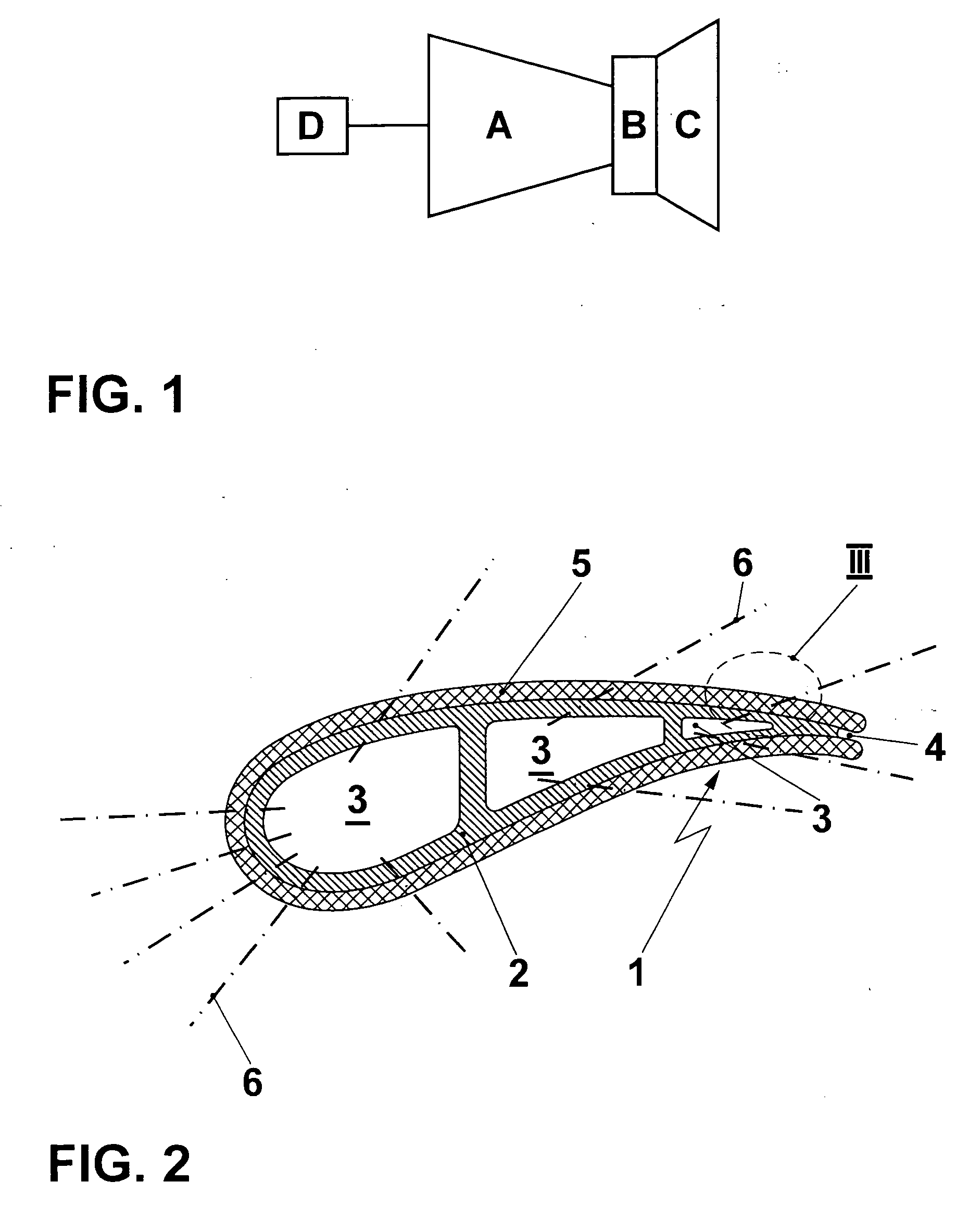
[0037]FIG. 1 shows a raw schematic of a gas turbine engine. The engine basically comprises a compressor A, to compress an airflow, a combustion chamber B, in which the compressed airflow is admixed with a fuel, and said fuel is burnt with said compressed airflow, thus producing a high temperature flue gas flow, which is then expanded in the turbine C, thereby providing usable power to drive the compressor A and optionally a load, such as for example generator D. Compressor A and turbine C comprise airfoils arranged in multiple stages of stationary vane rows and moving blade rows. In particular the airfoils of the first turbine stages are subject to high thermal loading during operation, and require cooling.

[0038] While the skilled person will readily appreciate the application of the invention to coated components of the combustor, and to very different composite components, which are applied in quite different fields than gas turbines, the invention is discussed in more detail in ...


PUM

PropertyMeasurementUnit
Angleaaaaaaaaaa
Angleaaaaaaaaaa
Frequencyaaaaaaaaaa

Abstract

A composite component (1), such as a turbine airfoil, includes a conductive portion (2), and a non-conductive portion (5), such as a thermal barrier coating or a wear protection coating, or both. In machining the component, a laser machining step is applied for machining the non-conductive portion, and an electro-machining step is applied for machining the conductive portion. The laser machining step is performed by applying preferably a high-frequency pulsed laser. The focussed laser beam working diameter (DL) is essentially smaller than the size of the contour (16) to be machined. The contour is scanned by the laser beam (9) along a pre-defined trace (17) thus literally inscribing the desired contour into the workpiece.

Description

METHOD OF PRODUCING A COMPOSITE COMPONENT [0001] This application is a Continuation of, and claims priority under 35 U.S.C. § 120 to, International Application number PCT / EP03 / 50214, by the inventors hereof, filed 4 Jun. 2003, and claims priority under 35 U.S.C. § 119 to GB application number 0213475.7, filed 12 Jun. 2002, the entireties of both of which are incorporated by reference herein.BACKGROUND OF THE INVENTION [0002] 1. Field of the Invention [0003] The present invention relates to a method for producing a composite component, to a composite component which is produced by applying said method, and to a turbomachine, in particular a gas turbine, comprising such a composite component. [0004] 2. Brief Description of the Related Art [0005] Electro discharge machining (EDM) and electro chemical machining (ECM) are well-known methods of machining. EDM and ECM are generally used to machine a workpiece in which high precision is required in machining high-hardness materials, at the ...

Claims


Application Information

Patent Timeline
IPC IPC(8): B23H9/10B23H9/14B23K26/38B23K26/40
CPCB23H9/10B23H9/14B23K26/0807B23K26/383B23K2201/001B23K26/388B23K26/407B23K26/408B23K26/409B23K26/386B23K26/082B23K26/384B23K26/40B23K26/389B23K2101/001B23K2103/172B23K2103/50B23K2103/52
Inventor LAVERS, FERGUSSELA, URI
Owner ANSALDO ENERGIA IP UK LTD
Why Eureka
Try Eureka